
Manual
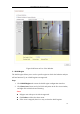
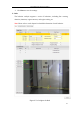
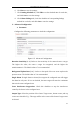
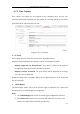


Table Of Contents
- Chapter 1 System Requirement
- Chapter 2 Network Connection
- Chapter 3 Access to the Network Camera
- Chapter 4 Wi-Fi Settings
- Chapter 5 Live View
- Chapter 6 Network Camera Configuration
- 6.1 Configuring Local Parameters
- 6.2 Configuring Time Settings
- 6.3 Configuring Network Settings
- 6.3.1 Configuring TCP/IP Settings
- 6.3.2 Configuring Port Settings
- 6.3.3 Configuring PPPoE Settings
- 6.3.4 Configuring DDNS Settings
- 6.3.5 Configuring SNMP Settings
- 6.3.6 Configuring 802.1X Settings
- 6.3.7 Configuring QoS Settings
- 6.3.8 Configuring UPnP™ Settings
- 6.3.9 Configuring Wireless Dial Settings
- 6.3.10 Email Sending Triggered by Alarm
- 6.3.11 Configuring NAT (Network Address Translation) Settings
- 6.3.12 Configuring FTP Settings
- 6.3.13 Platform Access
- 6.3.14 HTTPS Settings
- 6.4 Configuring Video and Audio Settings
- 6.5 Configuring Image Parameters
- 6.6 Configuring and Handling Alarms
- 6.6.1 Configuring Motion Detection
- 6.6.2 Configuring Video Tampering Alarm
- 6.6.3 Configuring Alarm Input
- 6.6.4 Configuring Alarm Output
- 6.6.5 Handling Exception
- 6.6.6 Configuring Other Alarm
- 6.6.7 Configuring Audio Exception Detection
- 6.6.8 Configuring Defocus Detection
- 6.6.9 Configuring Scene Change Detection
- 6.6.10 Configuring Face Detection
- 6.6.11 Configuring Line Crossing Detection
- 6.6.12 Configuring Intrusion Detection
- 6.6.13 Configuring Region Entrance Detection
- 6.6.14 Configuring Region Exiting Detection
- 6.6.15 Configuring Unattended Baggage Detection
- 6.6.16 Configuring Object Removal Detection
- 6.7 VCA Configuration
- Chapter 7 Storage Settings
- Chapter 8 Counting
- Chapter 9 Road Traffic
- Chapter 10 Playback
- Chapter 11 Log Searching
- Chapter 12 Others
- Appendix

User Manual of Network Camera
113
Steps:
1. Click Rule Tab to enter the rule configuration interface.
2. Check the checkbox of the single rule to enable the rule for behavior analysis.
3. Select the rule type, set the filter type, and then draw the line / area on the live
video for the single rule.
Filter type: Pixels and Actual Size are selectable. If Pixels is selected, draw
the area of maximum size and minimum size on the live video for each rule.
If Actual Size is selected, input the length and width of the maximum size and
minimum size. Only the target whose size is between the minimum value and
maximum value will trigger the alarm.
Note: Make sure the camera calibration is configured if actual size is selected.
Detection Target: Select Human or Vehicle as the detection target. You can
also select All to detect all the objects as the target.
Draw line / area: For line crossing detection, you have to draw a line, and
select the crossing direction, which is bidirectional, A-to-B, or B-to-A. For
other events such as intrusion, region entrance, region exiting, etc., you have
to left click on the live video to set the end points of the area and right click to
finish the area drawing.
Note: If the live view is stopped, the detection area / line cannot be draw and
the rules cannot be set.
4. Check the checkbox of the combined rule to enable the rule for behavior
analysis.
5. Select two configured single rules as the Rule A and Rule B of the combined
rule, set the minimum and maximum time interval for the two single rules,
and then select the trigger order of the single rules for alarm filtering.
Notes:
If you select the rule type as None, the rule option is invalid, and no
behavior analysis can be configured.
The trigger order of the single rules for alarm filtering can be set as In
Ascending Order or In Ascending/Descending Order.
Up to 8 single rules and 2 combined rules are configurable. And the line
crossing, intrusion, region exiting and region entrance are supported for
the combined rules.