
User Manual


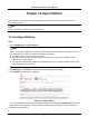


Table Of Contents
- Chapter 1 System Requirement
- Chapter 2 Device Activation and Accessing
- Chapter 3 Live View
- 3.1 Live View Parameters
- 3.1.1 Enable and Disable Live View
- 3.1.2 Adjust Aspect Ratio
- 3.1.3 Live View Stream Type
- 3.1.4 Select the Third-Party Plug-in
- 3.1.5 Light
- 3.1.6 Count Pixel
- 3.1.7 Start Digital Zoom
- 3.1.8 Auxiliary Focus
- 3.1.9 Lens Initialization
- 3.1.10 Quick Set Live View
- 3.1.11 Lens Parameters Adjustment
- 3.1.12 Conduct 3D Positioning
- 3.2 Set Transmission Parameters
- 3.3 Set Smooth Streaming
- 3.1 Live View Parameters
- Chapter 4 Video and Audio
- Chapter 5 Video Recording and Picture Capture
- Chapter 6 Event and Alarm
- 6.1 Basic Event
- 6.2 Smart Event
- 6.2.1 Detect Audio Exception
- 6.2.2 Set Defocus Detection
- 6.2.3 Detect Scene Change
- 6.2.4 Set Face Detection
- 6.2.5 Set Video Loss
- 6.2.6 Set Intrusion Detection
- 6.2.7 Set Line Crossing Detection
- 6.2.8 Set Region Entrance Detection
- 6.2.9 Set Region Exiting Detection
- 6.2.10 Set Unattended Baggage Detection
- 6.2.11 Set Object Removal Detection
- 6.2.12 Draw Area
- 6.2.13 Set Size Filter
- Chapter 7 Network Settings
- Chapter 8 Arming Schedule and Alarm Linkage
- Chapter 9 System and Security
- 9.1 View Device Information
- 9.2 Search and Manage Log
- 9.3 Simultaneous Login
- 9.4 Import and Export Configuration File
- 9.5 Export Diagnose Information
- 9.6 Reboot
- 9.7 Restore and Default
- 9.8 Upgrade
- 9.9 View Open Source Software License
- 9.10 Wiegand
- 9.11 Metadata
- 9.12 Time and Date
- 9.13 Set RS-485
- 9.14 Set RS-232
- 9.15 Power Consumption Mode
- 9.16 External Device
- 9.17 Security
- 9.18 Certificate Management
- 9.19 User and Account
- Chapter 10 Allocate VCA Resource
- Chapter 11 Open Platform
- Chapter 12 Smart Display
- Chapter 13 Set EPTZ
- Chapter 14 Pattern Linkage
- A. Device Command
- B. Device Communication Matrix

Network Camera User Manual
6
Chapter 14 Pattern Linkage
After the pattern linkage is set, the device can link the captured faces and human bodies
information from different channels.
Note
The function is only supported by multichannel devices.
14.1 Set Pattern Linkage
After the pattern linkage is set, the device can link the captured faces, human bodies and vehicles
information from different channels.
Before You Start
See Switch Smart Mode, check Pattern Mode.
Steps
1. Go to Configuration → Pattern Linkage → Calibration.
2. Click Add Point, Move the point in camera 1 to a reference in the image, and move the point
with the same number in camera 2 to the corresponding reference.
Delete Point
Delete all the selected points.
Clear All
Delete all the points.
3. Repeat step 2 to move the added points to the different references. You are recommended to
add at least 12 calibration points.
Note
● The points should be scattered and 3/4 points cannot be on one line.
● The device supports 4 to 64 calibration points.
4. Click Parity to check the points in the camera 1 and camera 2 are in the same reference
position. If not, adjust the point or calibrate the point again.
● If the channel 2 and channel 1 is in the same reference point, the calibration is succeeded.
● If the channel 2 and channel 1 isn't in the same reference point, the calibration failed. Repeat
step2 to adjust the points or calibrate again.
5. Click Rule, check Enable Pattern Linkage.
6. Click Save.