
User Manual
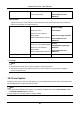


Table Of Contents
- Chapter 1 System Requirement
- Chapter 2 Device Activation and Accessing
- Chapter 3 Live View
- 3.1 Live View Parameters
- 3.1.1 Enable and Disable Live View
- 3.1.2 Adjust Aspect Ratio
- 3.1.3 Live View Stream Type
- 3.1.4 Select the Third-Party Plug-in
- 3.1.5 Light
- 3.1.6 Count Pixel
- 3.1.7 Start Digital Zoom
- 3.1.8 Auxiliary Focus
- 3.1.9 Lens Initialization
- 3.1.10 Quick Set Live View
- 3.1.11 Lens Parameters Adjustment
- 3.1.12 Conduct 3D Positioning
- 3.2 Set Transmission Parameters
- 3.3 Set Smooth Streaming
- 3.1 Live View Parameters
- Chapter 4 Video and Audio
- Chapter 5 Video Recording and Picture Capture
- Chapter 6 Event and Alarm
- 6.1 Basic Event
- 6.2 Smart Event
- 6.2.1 Detect Audio Exception
- 6.2.2 Set Defocus Detection
- 6.2.3 Detect Scene Change
- 6.2.4 Set Face Detection
- 6.2.5 Set Video Loss
- 6.2.6 Set Intrusion Detection
- 6.2.7 Set Line Crossing Detection
- 6.2.8 Set Region Entrance Detection
- 6.2.9 Set Region Exiting Detection
- 6.2.10 Set Unattended Baggage Detection
- 6.2.11 Set Object Removal Detection
- 6.2.12 Draw Area
- 6.2.13 Set Size Filter
- Chapter 7 Network Settings
- Chapter 8 Arming Schedule and Alarm Linkage
- Chapter 9 System and Security
- 9.1 View Device Information
- 9.2 Search and Manage Log
- 9.3 Simultaneous Login
- 9.4 Import and Export Configuration File
- 9.5 Export Diagnose Information
- 9.6 Reboot
- 9.7 Restore and Default
- 9.8 Upgrade
- 9.9 View Open Source Software License
- 9.10 Wiegand
- 9.11 Metadata
- 9.12 Time and Date
- 9.13 Set RS-485
- 9.14 Set RS-232
- 9.15 Power Consumption Mode
- 9.16 External Device
- 9.17 Security
- 9.18 Certificate Management
- 9.19 User and Account
- Chapter 10 Allocate VCA Resource
- Chapter 11 Open Platform
- Chapter 12 Smart Display
- Chapter 13 Set EPTZ
- Chapter 14 Pattern Linkage
- A. Device Command
- B. Device Communication Matrix

Network Camera User Manual
92
5. Adjust the zoom ratio of the camera so that the size of the vehicle in the image is close to that
of the red frame. Only the position of red frame is adjustable.
Note
Only 1 license plate can be captured at one time for each lane.
6. Select Region and Country/Region.
7. Select the license plate information upload mode.
Entrance/Exit
The license plate information of the detected vehicle will be uploaded
when the vehicle passes the detection area and triggers the detection
in entrance/exit.
City Street
The license plate information of the detected vehicle will be uploaded
when the vehicle passes the detection area and triggers the detection
in city streets.
Alarm Input
It means the input alarm will trigger a license plate capture and
recognition action.
Note
When Alarm Input is selected, the alarm input A<-1 will automatically be assigned to trigger
vehicle detection and its alarm type is always NO.If the A<-1 alarm input is used to trigger vehicle
detection, it can not be used for other basic events.When Alarm Input is selected and saved,
previously configured linkage method for A<-1 will be canceled.
8. Select the Detection mode.
9. Check Remove Duplicated License Plates ans set the Time Interval. The default time interval is
4 minutes.
Note
Up to 8 license plates are supported.
10. Set arming schedule and linkage method. For the arming schedule settings, refer to Set Arming
Schedule. For the linkage method settings, refer to Linkage Method Settings.
11. Click Save.