
User Manual
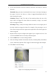
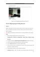
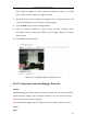
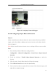
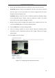
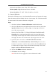
Table Of Contents
- Chapter 1 System Requirement
- Chapter 2 Network Connection
- Chapter 3 Access to the Network Camera
- Chapter 4 Wi-Fi Settings
- Chapter 5 Live View
- Chapter 6 Network Camera Configuration
- 6.1 Configuring Local Parameters
- 6.2 Configuring Time Settings
- 6.3 Configuring Network Settings
- 6.3.1 Configuring TCP/IP Settings
- 6.3.2 Configuring Port Settings
- 6.3.3 Configuring PPPoE Settings
- 6.3.4 Configuring DDNS Settings
- 6.3.5 Configuring SNMP Settings
- 6.3.6 Configuring 802.1X Settings
- 6.3.7 Configuring QoS Settings
- 6.3.8 Configuring UPnP™ Settings
- 6.3.9 Configuring Wireless Dial Settings
- 6.3.10 Email Sending Triggered by Alarm
- 6.3.11 Configuring NAT (Network Address Translation) Settings
- 6.3.12 Configuring FTP Settings
- 6.3.13 Platform Access
- 6.3.14 HTTPS Settings
- 6.4 Configuring Video and Audio Settings
- 6.5 Configuring Image Parameters
- 6.6 Configuring and Handling Alarms
- 6.6.1 Configuring Motion Detection
- 6.6.2 Configuring Video Tampering Alarm
- 6.6.3 Configuring Alarm Input
- 6.6.4 Configuring Alarm Output
- 6.6.5 Handling Exception
- 6.6.6 Configuring Other Alarm
- 6.6.7 Configuring Audio Exception Detection
- 6.6.8 Configuring Defocus Detection
- 6.6.9 Configuring Scene Change Detection
- 6.6.10 Configuring Face Detection
- 6.6.11 Configuring Line Crossing Detection
- 6.6.12 Configuring Intrusion Detection
- 6.6.13 Configuring Region Entrance Detection
- 6.6.14 Configuring Region Exiting Detection
- 6.6.15 Configuring Unattended Baggage Detection
- 6.6.16 Configuring Object Removal Detection
- 6.7 VCA Configuration
- Chapter 7 Storage Settings
- Chapter 8 Counting
- Chapter 9 Road Traffic
- Chapter 10 Playback
- Chapter 11 Log Searching
- Chapter 12 Others
- Appendix

User Manual of Network Camera
110
image to the surveillance center when a VCA alarm occurs.
Picture Quality: High, Medium and Low are selectable.
Picture Resolution: CIF, 4CIF, 720P, and 1080P are selectable.
Camera Calibration
Perform the following steps to three-dimensionally measure and quantize the image
from the camera, and then calculate the size of every target. The VCA detection will
be more accurate if the camera calibration is configured.
Steps:
1. Check the checkbox of Camera Calibration to enable this function.
2. Select the calibration mode as Input Basic Data or Draw on Live View Video.
Input Basic Data: Input the mounting height, viewing angle, and horizon
ratio of the camera manually.
Draw on Live View Video: Click Draw Verification Line (Horizontal) /
(Vertical) to draw a horizontal/vertical line in the live view, and input the
actual length in Real Length field. With the drawn reference lines and their
real length, the camera can conclude other objects appear in the live view.
3. (Optional) Check the checkbox of Enable Verification of Camera
Calibration, click the Horizontal Verify / Vertical Verify button to draw a
horizontal / vertical line on the live video, and then click the Calibrate button
to calculate the line length. Compare the calculated line length to the actual
length to verify the calibration information you set.
4. You can click Delete to delete the drawn lines.
5. Click Save to save the settings.
Note: If the live view is stopped, the camera calibration is invalid.