
User Manual
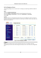


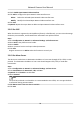
Table Of Contents
- Initiatives on the Use of Video Products
- Legal Information
- Chapter 1 Device Activation and Accessing
- Chapter 2 Network Camera Configuration
- 2.1 Update Firmware
- 2.2 Symbol Conventions
- 2.3 Safety Instruction
- 2.4 System Requirement
- 2.5 Live View
- 2.6 Video and Audio
- 2.7 Video Recording and Picture Capture
- 2.8 Event and Alarm
- 2.9 Network Settings
- 2.10 Arming Schedule and Alarm Linkage
- 2.11 System and Security
- 2.11.1 View Device Information
- 2.11.2 Search and Manage Log
- 2.11.3 Simultaneous Login
- 2.11.4 Import and Export Configuration File
- 2.11.5 Export Diagnose Information
- 2.11.6 Reboot
- 2.11.7 Restore and Default
- 2.11.8 Upgrade
- 2.11.9 Device Auto Maintenance
- 2.11.10 View Open Source Software License
- 2.11.11 Wiegand
- 2.11.12 Metadata
- 2.11.13 Time and Date
- 2.11.14 Set RS-485
- 2.11.15 Set RS-232
- 2.11.16 Power Consumption Mode
- 2.11.17 External Device
- 2.11.18 Security
- 2.11.19 Certificate Management
- 2.11.20 User and Account
- 2.12 VCA Resource
- 2.13 Smart Display
- 2.14 EPTZ
- 2.15 Image Stitching
- Appendix A. FAQ
- Appendix B. Device Command
- Appendix C. Device Communication Matrix

Set Port Mapping on Router
The following sengs are for a certain router. The sengs vary depending on dierent models of
routers.
Steps
1.
Select the WAN
Connecon Type.
2.
Set the IP Address, Subnet Mask and other network parameters of the router.
3.
Go to Forwarding → Virtual Severs , and input the Port Number and IP Address.
4.
Click Save.
Example
When the cameras are connected to the same router, you can
congure the ports of a camera as
80, 8000, and 554 with IP address 192.168.1.23, and the ports of another camera as 81, 8001, 555,
8201 with IP 192.168.1.24.
Figure 2-13 Port Mapping on Router
Note
The port of the network camera cannot conict with other ports. For example, some web
management port of the router is 80. Change the camera port if it is the same as the management
port.
Network Camera User Manual
65