Network Turret Camera Quick Start Guide 0
Network Turret Camera·Quick Start Guide Quick Start Guide © 2020 Hangzhou Hikvision Digital Technology Co., Ltd. All rights reserved. This Manual is the property of Hangzhou Hikvision Digital Technology Co., Ltd. or its affiliates (hereinafter referred to as “Hikvision”), and it cannot be reproduced, changed, translated, or distributed, partially or wholly, by any means, without the prior written permission of Hikvision.
Network Turret Camera·Quick Start Guide TO THE MAXIMUM EXTENT PERMITTED BY APPLICABLE LAW, THIS MANUAL AND THE PRODUCT DESCRIBED, WITH ITS HARDWARE, SOFTWARE AND FIRMWARE, ARE PROVIDED “AS IS” AND “WITH ALL FAULTS AND ERRORS”. HIKVISION MAKES NO WARRANTIES, EXPRESS OR IMPLIED, INCLUDING WITHOUT LIMITATION, MERCHANTABILITY, SATISFACTORY QUALITY, OR FITNESS FOR A PARTICULAR PURPOSE. THE USE OF THE PRODUCT BY YOU IS AT YOUR OWN RISK.
Network Turret Camera·Quick Start Guide PARTIES, INCLUDING WITHOUT LIMITATION, RIGHTS OF PUBLICITY, INTELLECTUAL PROPERTY RIGHTS, OR DATA PROTECTION AND OTHER PRIVACY RIGHTS. YOU SHALL NOT USE THIS PRODUCT FOR ANY PROHIBITED END-USES, INCLUDING THE DEVELOPMENT OR PRODUCTION OF WEAPONS OF MASS DESTRUCTION, THE DEVELOPMENT OR PRODUCTION OF CHEMICAL OR BIOLOGICAL WEAPONS, ANY ACTIVITIES IN THE CONTEXT RELATED TO ANY NUCLEAR EXPLOSIVE OR UNSAFE NUCLEAR FUEL-CYCLE, OR IN SUPPORT OF HUMAN RIGHTS ABUSES.
Network Turret Camera·Quick Start Guide encouraged to try to correct the interference by one or more of the following measures: —Reorient or relocate the receiving antenna. —Increase the separation between the equipment and receiver. —Connect the equipment into an outlet on a circuit different from that to which the receiver is connected. —Consult the dealer or an experienced radio/TV technician for help. FCC Conditions This device complies with part 15 of the FCC Rules.
Network Turret Camera·Quick Start Guide 2006/66/EC (battery directive): This product contains a battery that cannot be disposed of as unsorted municipal waste in the European Union. See the product documentation for specific battery information. The battery is marked with this symbol, which may include lettering to indicate cadmium (Cd), lead (Pb), or mercury (Hg). For proper recycling, return the battery to your supplier or to a designated collection point. For more information, see: www.recyclethis.info.
Network Turret Camera·Quick Start Guide Warnings Warnings Follow these safeguards to prevent serious injury or death. Cautions Cautions Follow these precautions to prevent potential injury or material damage. Warnings ● Proper configuration of all passwords and other security settings is the responsibility of the installer and/or end-user. ● In the use of the product, you must be in strict compliance with the electrical safety regulations of the nation and region.
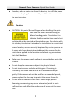
Network Turret Camera·Quick Start Guide ● If smoke, odor or noise rise from the device, turn off the power at once and unplug the power cable, and then please contact the service center. Cautions ● CAUTION: Hot parts! Burned fingers when handling the parts. Wait one-half hour after switching off before handling parts. This sticker is to indicate that the marked item can be hot and should not be touched without taking care.
Network Turret Camera·Quick Start Guide ● The sensor may be burned out by a laser beam, so when any laser equipment is in using, make sure that the surface of sensor will not be exposed to the laser beam. ● Do not place the camera in extremely hot, cold (the operating temperature shall be -30°C to 60°C), dusty or damp locations, and do not expose it to high electromagnetic radiation. ● To avoid heat accumulation, good ventilation is required for operating environment.
Network Turret Camera·Quick Start Guide ● Improper replacement of the battery with an incorrect type may defeat a safeguard (for example, in the case of some lithium battery types). ● Do not dispose of the battery into fire or a hot oven, or mechanically crush or cut the battery, which may result in an explosion. ● Do not leave the battery in an extremely high temperature surrounding environment, which may result in an explosion or the leakage of flammable liquid or gas.
Network Turret Camera·Quick Start Guide Table of Contents 1 Appearance Description ............................................................ 11 1.1 Type I .................................................................................. 11 1.2 Type II ................................................................................. 12 1.3 Type III ................................................................................ 13 1.4 Type IV .............................................................
Network Turret Camera·Quick Start Guide 1 Appearance Description 1.1 Type I 1 4 6 2 3 5 Figure 1-1 Overview of Type I Turret Camera Table 1-1 Description No. Description No.
Network Turret Camera·Quick Start Guide 1.2 Type II 1 4* 5 2 7 3 6 Figure 1-2 Overview of Type II Turret Camera Table 1-2 Description No. Description No. Description 1 Trim Ring 4* Photosensitive Resistance 2 Enclosure 5 Camera 3 Mounting Base 6 Power Cord 7 10M/100M Self-adaptive Ethernet Interface Note: The item marked with the "*" is only supported by certain camera models.
Network Turret Camera·Quick Start Guide 1.3 Type III 1 4 2 5 6 3 10 11 7 8 9 Figure 1-3 Overview of Type III Turret Camera Table 1-3 Description No. Description No.
Network Turret Camera·Quick Start Guide No. Description 6 10M/100M self-adaptive Ethernet Interface No. Description Note: Press Reset button about 10s when the camera is power on or rebooting to restore the default settings, including the user name, password, IP address, port No., etc. 1.4 Type IV 1 4 2 5 6 3 10 10 9 9 Figure 1-4 Type IV Turret Camera Table 1-4 Description No. Description No.
Network Turret Camera·Quick Start Guide No. Description No. Description Ethernet Interface (PoE) 3 Mounting Base 7 RST (Reset) Button 4 Camera 8 Memory Card Slot Notes: ● For this type IV camera, the layout of memory card slot and reset button may be different from model to model. ● Press Reset button about 10 s when the camera is power on or rebooting to restore the default settings, including the user name, password, IP address, and port No., etc. 1.
Network Turret Camera·Quick Start Guide 1 2 3 6 4 5 Figure 1-6 Type VI Camera Overview Table 1-5 Description No. Description No. Description 1 Enclosure 5 Lock Button 2 Camera 6 Network Interface 3 Memory Card Slot 7 Power Interface 4 Mounting Base Notes: Press Reset button about 10 s when the camera is power on or rebooting to restore the default settings, including the user name, password, IP address, and port No., etc.
Network Turret Camera·Quick Start Guide 2 Installation Before you start: ● Make sure the device in the package is in good condition and all the assembly parts are included. ● The standard power supply is 12 VDC or PoE (802.3af). Please make sure your power supply matches with your camera. ● Make sure all the related equipment is power-off during the installation. ● Check the specification of the products for the installation environment.
Network Turret Camera·Quick Start Guide 2). Rotate the trim ring anticlockwise to take it off from the camera. 3). Separate the camera and the enclosure. ③ Trim Ring ② Camera Lock Screw ① Mounting Base Figure 2-1 Disassemble the Camera Drill the screw holes and the cable hole on the ceiling according to the drill template.
Network Turret Camera·Quick Start Guide There are two cable outlet methods. One is to route the cables through the cable hole, and the other is to route the cables through the side outlet shown below. Figure 2-3 Side Outlet Notes: Three side outlets on the enclosure are selectable, which makes routing the cables easier instead of drilling a cable hole on the ceiling. Use a plier to remove the plastic and route the cables through the hole.
Network Turret Camera·Quick Start Guide Figure 2-4 Secure the Mounting to the Ceiling Connect the corresponding power/network cable and then install the camera to the mounting base with the supplied screws. Rotate the camera to secure it. Figure 2-5 Secure the Camera to the Mounting Base Adjust the Lens. 1). Loosen the lock screw. Lock Screw Figure 2-6 Loosen Lock Screw 2). Rotate the enclosure to adjust the pan angle; rotate the camera to adjust the tilt angle.
Network Turret Camera·Quick Start Guide P Direction 360o T Direction 0o to 75o R Direction 360o Figure 2-7 Adjust the Lens 3). Tighten the lock screw to fix the optimum surveillance angle. Attach the trim ring to the camera and rotate the trim ring clockwise to get it secured. Trim Ring Figure 2-8 Install the Trim Ring 2.1.2 Type II Steps: Disassemble the camera.
Network Turret Camera·Quick Start Guide 4). Rotate the enclosure anticlockwise to take it off from the camera. 5). Separate the camera, the mounting base, and the trim ring. ② Trim Ring ① Camera Mounting Base Figure 2-9 Disassemble the Camera Drill the screw holes and the cable hole on the ceiling according to the drill template.
Network Turret Camera·Quick Start Guide There are two cable outlet methods. One is to route the cables through the cable hole, and the other is to route the cables through the side outlet shown below. Figure 2-11 Side Outlet Notes: Three side outlets on the enclosure are selectable, which makes routing the cables easier instead of drilling a cable hole on the ceiling. Use a plier to remove the plastic and route the cables through the hole.
Network Turret Camera·Quick Start Guide Install the camera along with the enclosure to the mounting base by anticlockwise rotating the camera. Rotate the enclosure to adjust the pan angle; rotate the camera to adjust the tilt angle. P Direction 360o T Direction 0o to 75o R Direction 360o Figure 2-13 Adjust the Lens Attach the trim ring to the camera and rotate the trim ring clockwise to get it secured. Trim Ring Figure 2-14 Install the Trim Ring 2.1.
Network Turret Camera·Quick Start Guide Disassemble the camera. 1). Rotate the trim ring anticlockwise to take it off from the camera. 2). Rotate the mounting base anticlockwise to take it off from the camera. 3). Separate the camera and the enclosure. Trim Ring ① ③ ② Enclosure Camera Mounting Base Figure 2-15 Disassemble the Camera Install the memory card. 1). Find the Micro SD/RST cover on the side of the camera. Micro SD/RST Cover Figure 2-16 Micro SD/RST Cover 2).
Network Turret Camera·Quick Start Guide microSD Card Figure 2-17 Memory Card Slot 3). Place the cover back. Stick the drill template on the installation place and drill the screw holes and the cable hole on the ceiling according to the drill template. Figure 2-18 The Drill Template Fix the mounting base to the ceiling with two supplied expansion screws.
Network Turret Camera·Quick Start Guide Figure 2-19 Install the Mounting Base Connect the corresponding power/network cable. Refer to the section 2.3 for the waterproof accessory installation if the camera is installed in the outdoor. Install the camera along with the enclosure to the mounting base by anticlockwise rotating the camera. Figure 2-20 Install the Camera Rotate the enclosure to adjust the pan angle; rotate the camera to adjust the tilt angle.
Network Turret Camera·Quick Start Guide 360° P Direction 0° to 75° T Direction 360° R Direction Figure 2-21 Adjust the Lens Attach the trim ring to the camera and rotate the trim ring clockwise to get it secured. Trim Ring Figure 2-22 Install the Trim Ring 2.1.4 Type IV Steps: Disassemble the camera. 1). Rotate the trim ring anticlockwise to take it off from the camera.
Network Turret Camera·Quick Start Guide 2). Loosen the fixing screw. Take the mounting base off from the camera and the enclosure. 3). Separate the camera and the enclosure. ① ③ Fixing Screw ② Figure 2-23 Disassemble the Camera Install memory card. 1). Unscrew the memory card slot cover. 2). Insert the memory card. Memory Card Figure 2-24 Install Memory Card 3). (Optional) to unmount the memory card, push to get it ejected. 4). Screw the memory card slot cover back.
Network Turret Camera·Quick Start Guide Paste the drill template to desired mounting place. Drill the screw holes (for expansion screws) and the cable hole on the ceiling according to the drill template. 5). Note: 6). If the camera is installed to a wooden wall, use self-tapping screws instead of expansion screws. Figure 2-25 Drill Template Fix the mounting base to the ceiling with two supplied screws.
Network Turret Camera·Quick Start Guide Connect the corresponding power/network cable. Refer to the section 2.3 for the waterproof accessory installation if the camera is installed in the outdoor. Install the camera along with the enclosure to the mounting base. Figure 2-27 Install the Camera Adjust the surveillance angle of the camera. Secure the fixing screw after adjustment.
Network Turret Camera·Quick Start Guide Figure 2-29 Install Trim Ring 2.1.5 Type V, VI Before You Start: The installation steps of the type V and type VI are similar and here take type V as an example to describe the steps. Steps: 1. Push the lock button to remove the bottom base. Push Figure 2-30 Remove the Bottom Base 2. Loosen the screws to remove the memory card slot cover. 3. Insert the memory card into the slot.
Network Turret Camera·Quick Start Guide Reset Button Memory Card Slot Figure 2-31 Insert the Memory Card into the Slot 4. Replace the slot cover with the screws. 5. Drill the screw holes and the cable hole on the ceiling according to the drill template. 54.3 54.3 14.5 39.7 3-Φ4.5 Φ125 14.5 Figure 2-32 The Drill Template 6. Fix the mounting base to the ceiling with the screws.
Network Turret Camera·Quick Start Guide Figure 2-33 Secure the Mounting to the Ceiling 7. Connect the corresponding power and network cables. 8. Install the camera to the mounting base with the screws. Figure 2-34 Secure the Camera to the Mounting Base 9. Adjust the Lens.
Network Turret Camera·Quick Start Guide Pan: 0 to 360° Tilt: 0 to 75° Rotation: 0 to 360° Figure 2-35 Adjust the Lens 2.2 Mounting with Brackets This camera series supports mounting with wall mounting bracket and pendant mounting bracket. We take Type IV camera as the demonstration example. 2.2.1 Wall Mounting The wall mount is not included in the package. You need to prepare one, if you adopt this mounting type. Steps: Mark the screw holes on desired mounting place.
Network Turret Camera·Quick Start Guide Figure 2-36 Dimension of Demonstrated Wall Mounting Bracket Drill four screw holes with a Φ10 mm drill. Route the cables and fix the bracket with four M6 expansion bolts. Disassemble the camera. Refer to step 1 in ceiling mounting of each camera type. Fix the mounting base to the cap of wall mount with 3 supplied self-tapping screws.
Network Turret Camera·Quick Start Guide Connect the corresponding power/network cable. Refer to the section 2.3 for the waterproof accessory installation if the camera is installed in the outdoor. Install the camera and the enclosure to the mounting base, adjust the surveillance angle, and fix the trim ring. Refer to corresponding steps in ceiling mounting of each camera type. Figure 2-38 Wall Mounting 2.2.2 Pendant Mounting The pendant mounting bracket is not included in the package.
Network Turret Camera·Quick Start Guide Cables Figure 2-39 Fix Pendant Mount Disassemble the camera. Refer to step 1 in ceiling mounting of each camera type. Fix the mounting base to the cap of the pendant mounting bracket with 3 supplied self-tapping screws. Mounting Base Cap Figure 2-40 Fix Mounting Base Screw the cap to the pendant mount.
Network Turret Camera·Quick Start Guide Pendant Mount Cap Figure 2-41 Install the Cap Connect the corresponding power/network cable. Refer to the section 2.3 for the waterproof accessory installation if the camera is installed in the outdoor. Install the camera and the enclosure to the mounting base, adjust the surveillance angle, and fix the trim ring. Refer to corresponding steps in ceiling mounting of each camera type.
Network Turret Camera·Quick Start Guide Figure 2-42 Pendant Mounting Waterproof Measures If the camera is installed outdoor, you should use the waterproof accessory or tapes to waterproof the cables. Otherwise, the cables might get wet or a short circuit occurs. 2.3.
Network Turret Camera·Quick Start Guide Steps: 1. Feed the network cable through ① and ③ in order. 2. Fix ② on the network cable between ① and ③. 3. Place ⑤ onto the end of ⑥, and plug the RJ45 male connector into RJ45 female connector. 4. Screw ③ to ⑥ clockwise. 5. Push ② into ③. 6. Secure ① with the ③ in clockwise direction. 2.3.2 Waterproof Other Cables After routing and connecting the cables, use the waterproof tapes to wrap up the cables.
Network Turret Camera·Quick Start Guide 3 Activate and Access Network Camera Scan the QR code to get Activate and Access Network Camera. Note that mobile data charges may apply if Wi-Fi is unavailable.
UD11150B-C 0