Quick Start Guide DS-2CD23xxxx-xx Network Turret Cameras
Copyright © 2020 Hangzhou Hikvision Digital Technology Co., Ltd. ALL RIGHTS RESERVED. Any and all information, including, among others, wordings, pictures, and graphs are the properties of Hangzhou Hikvision Digital Technology Co., Ltd., or its subsidiaries (hereinafter referred to be “Hikvision”). This user manual (hereinafter referred to be “the Manual”) cannot be reproduced, changed, translated, or distributed, partially or wholly, by any means, without the prior written permission of Hikvision.
device, pursuant to part 15 of the FCC Rules. These limits are designed to provide reasonable protection against harmful interference in a residential installation. This equipment generates, uses, and can radiate radio frequency energy and, if not installed and used in accordance with the instructions, may cause harmful interference to radio communications. However, there is no guarantee that interference will not occur in a particular installation.
• Cautions: Injury or equipment damage may occur if any of the cautions are neglected. Warnings Follow these safeguards to prevent serious injury or death. Cautions Follow these precautions to prevent potential injury or material damage. Warnings • Proper configuration of all passwords and other security settings is the responsibility of the installer and/or end user. • In the use of the product, you must be in strict compliance with the electrical safety regulations of the nation and region.
• To avoid heat accumulation, good ventilation is required for the operating environment. • Keep the camera away from liquids while in use. • While in delivery, pack the camera in its original packing or packing of the same material. • Regular Part Replacement: A few equipment parts (e.g., electrolytic capacitor) must be replaced regularly according to their average life.
Table of Contents 1 2 3 4 5 Appearance ........................................................................................................................................ 7 1.1 Type I ................................................................................................................................................. 7 1.2 Type II ................................................................................................................................................ 8 1.
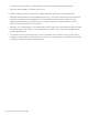
1 Appearance This turret camera series has four appearance types. 1.1 Type I Figure 1, Overview of Type I Turret Camera Table 1-1 Description No. Description 1 Trim Ring 2 Enclosure 3 Mounting Base QSG DS-2CD23xxxx-xx Turret 051420NA No.
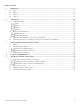
1.2 Type II Figure 2, Overview of Type II Turret Camera Table 1-2 Description No. Description 1 Trim Ring 2 Enclosure 3 Mounting Base QSG DS-2CD23xxxx-xx Turret 051420NA No.
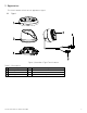
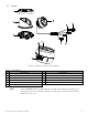
1.3 Type III Figure 3, Overview of Type III Turret Camera Table 1-3 Description No. Description No. 1 Trim Ring 7 2 Enclosure 8 3 Mounting Base 9 4 Camera 10 5 Power Cord 11 6 10M/100M Self-Adaptive Ethernet Interface NOTE: Description Audio Output 1-ch Alarm Input and 1-ch Alarm Output RST (Reset) Button Memory Card Slot Mic Press the Reset button for approximately 10s when the camera is powering on or rebooting to restore the default settings, including the user name, password, IP address, port no.
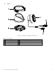
1.4 Type IV Figure 4, Type IV Turret Camera Table 1-4 Description No. Description 1 Trim Ring 2 Enclosure 3 Mounting Base 4 Camera NOTES: No. 5 6 7 8 Description Power Cord 10M/100M Self-Adaptive Ethernet Interface (PoE) RST (Reset) Button Memory Card Slot For type IV cameras, the memory card slot and reset button locations may differ by model.
• Make sure that the wall is strong enough to withstand four times the weight of the camera and the bracket. • For cameras that support IR, make sure that there is no reflective surface too close to the camera lens. The IR light from the camera may reflect back into the lens causing reflection. 2.1 Ceiling Mounting Type I 1. Disassemble the camera. 1). Loosen the lock screw on the mounting base, and remove the base from the camera. 2). Rotate the trim ring counterclockwise, and take it off the camera.
Figure 6, Drill Template NOTE: There are two cable outlet methods. One is to route the cables through the cable hole, and the other is to route the cables through the side outlet as shown below.
NOTE: Three side outlets on the enclosure are selectable, which makes routing the cables easier instead of drilling a cable hole on the ceiling. Use a plier to remove the plastic, and route the cables through the hole. 3. Affix the mounting base to the ceiling with the supplied expansion screws. Figure 8, Secure the Mounting to the Ceiling 4. Connect the corresponding power/network cable, and then install the camera to the mounting base with the supplied screws. Rotate the camera to secure it.
Figure 10, Loosen Lock Screw 2). Rotate enclosure to adjust the pan angle; rotate camera to adjust the tilt angle. Figure 11, Adjust the Lens 3). Tighten the lock screw to fix the optimum surveillance angle. 6. Attach the trim ring to the camera and rotate the trim ring clockwise to secure it.
Type II 1. Disassemble the camera. 1). Rotate the enclosure counterclockwise to remove it from the camera. 2). Separate the camera, the mounting base, and the trim ring. Figure 13, Disassemble the Camera 2. Drill the screw holes and the cable hole on the ceiling according to the drill template.
NOTE: There are two cable outlet methods. One is to route the cables through the cable hole, and the other is to route the cables through the side outlet shown below. Figure 15, Side Outlet NOTE: Three side outlets on the enclosure are selectable, which makes routing the cables easier instead of drilling a cable hole on the ceiling. Use a plier to remove the plastic, and route the cables through the hole. 3. Fix the mounting base to the ceiling with the supplied expansion screws.
Figure 17, Adjust the Lens 7. Attach the trim ring to the camera, and rotate it clockwise to secure it. Figure 18, Install the Trim Ring Type III 1. Disassemble the camera. 1). Rotate the trim ring counterclockwise to take it off of the camera. 2). Rotate the mounting base counterclockwise to take it off of the camera. 3). Separate the camera and the enclosure.
2. Install the memory card. 1). Locate the microSD/RST cover on the side of the camera. MicroSD/RST Cover Figure 20, Micro SD/RST Cover 2). Take off the cover, and insert the microSD card into the card slot. Figure 21, Memory Card Slot 3). Replace the cover. 3. Secure the drill template to the installation location, and drill the screw holes and the cable hole on the ceiling according to the drill template.
Figure 22, Drill Template 4. Affix the mounting base to the ceiling with two supplied expansion screws. Figure 23, Fix Mounting Base to Ceiling 5. Connect the corresponding power/network cable. Refer to section 2.3 for waterproof accessory installation if the camera is installed outdoors. 6. Attach the camera along with the enclosure to the mounting base by rotating the camera anticlockwise.
Figure 24, Install the Camera 7. Rotate the enclosure to adjust the pan angle; rotate the camera to adjust the tilt angle. Figure 25, Adjust the Lens 8. Attach the trim ring to the camera, and rotate the trim ring clockwise to secure it. Figure 26, Install the Trim Ring Type IV 1. Disassemble the camera. 1). Rotate the trim ring counterclockwise to take it off of the camera. 2). Loosen the fixing screw. Take the mounting base off of the camera and enclosure.
3). Separate the camera and the enclosure. Figure 27, Disassemble the Camera 2. Install memory card. 1). Unscrew the memory card slot cover. 2). Insert the memory card. Figure 28, Install Memory Card 3). (Optional) to unmount the memory card, push it in to eject it. 4). Screw the memory card slot cover back on. 3. Paste the drill template to desired mounting location. 4. Drill the screw holes (for expansion screws) and the cable hole on the ceiling according to the drill template.
Figure 29, Drill Template 5. Fix the mounting base to the ceiling with two supplied screws. Figure 30, Fix Mounting Base 6. Connect the corresponding power/network cable. Refer to section 2.3 for waterproof accessory installation if the camera is installed outdoors. 7. Attach the camera and enclosure to the mounting base.
Figure 31, Install the Camera 8. Adjust the surveillance angle of the camera. Secure the fixing screw after adjustment. Figure 32, Adjust Surveillance Angle 9. Attach the trim ring to the camera, and rotate the trim ring clockwise to secure it. Figure 33, Install Trim Ring 2.2 Mounting with Brackets This camera series supports mounting with a wall mounting bracket and a pendant mounting bracket. We take a Type IV camera as the demonstration example.
Wall Mounting A wall mount is not included in the package. You must purchase one separately if you use this mounting method. 1. Mark the screw holes on the desired mounting location. Figure 34, Dimensions of Typical Wall Mounting Bracket 2. Drill four screw holes with a Ø10 mm drill. 3. Route the cables and fix the bracket with four M6 expansion bolts. 4. Disassemble the camera. NOTE: Refer to step 1 in the specifc camera type’s ceiling mounting section. 5.
Figure 35, Fix Mounting Base 6. Connect the corresponding power/network cable. Refer to section 2.3 for waterproof accessory installation if the camera is installed outdoors. 7. Install the camera and the enclosure to the mounting base, adjust the surveillance angle, and fix the trim ring. NOTE: Refer to the specific camera type’s corresponding ceiling mounting steps. Figure 36, Wall Mounting Pendant Mounting A pendant mounting bracket is not included in the package.
Figure 37, Fix Pendant Mount 4. Disassemble the camera. NOTE: Refer to step 1 of the specific camera type’s ceiling mounting section. 5. Fix the mounting base to the pendant mounting bracket cap with three supplied selftapping screws. Figure 38, Fix Mounting Base 6. Screw the cap to the pendant mount.
Figure 39, Install the Cap 7. Connect the corresponding power/network cable. Refer to section 2.3 for waterproof accessory installation if the camera is installed outdoors. 8. Install the camera and the enclosure to the mounting base, adjust the surveillance angle, and fix the trim ring. NOTE: Refer to corresponding steps in each camera type’s ceiling mounting section.
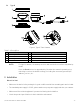
2.3 Network Cable Waterproof Accessory Installation Purpose If the camera is installed outdoors, you can use the waterproof accessory for the network cable after the camera is secured on the installation surface. Figure 41, Waterproof Accessory Components Table 2-1 Components No. Components 1 Camera’s Network Interface Socket 2 O-Type Gasket 3 Network Plug 4 Waterproof Endcap 5 Waterproof Rubber Gasket 6 Lock Nut 7 Network Cable from Router/Switch 1.
Figure 42, Waterproof Accessory Installation 2.4 Special Instructions for Attaching Camera to a CB140PT Conduit Base Some cameras (e.g., DS-2CD23x5G1, DS-2CD23x7G1, DS-2TD1217-2/3/6/V1, DS-2CD23x6G2, DS2CD23x6G1, DS-2CD23x7G1, DS-2CD23x6G2, and others) require the following steps to install a CB140PT conduit base accessory. 1. Twist to remove the trim ring from the camera mounting base. 2. Loosen the pressure clamp locking screw on the mounting base. 3. Slide the pressure clamp away from the mounting base.
Figure 43, Attaching a CB140PT Conduit Base to a Select Camera Model (Typical) 3 Setting the Network Camera over the LAN NOTE: You shall acknowledge that the use of the product with Internet access might be under network security risks. For avoidance of any network attacks and information leakage, please strengthen your own protection. If the product does not work properly, contact your dealer or the nearest service center for help.
3.1 Wiring Connect the camera to the network according to the following figures. Figure 44, Connecting Directly Figure 45, Connecting via a Switch or a Router 3.2 Activating the Camera You are required to activate the camera first by setting a strong password for it before you can use it. Activation via Web browser, activation via SADP, and activation via client software are all supported.
1. Power on the camera. 2. Connect the camera to your computer or the switch/router which your computer connects to. 3. Input the IP address into the Web browser’s address bar and press Enter to enter the activation interface. NOTES: The default IP address of the camera is 192.168.1.64. The computer and the camera should belong to the same subnet. For cameras that enable DHCP by default, use the SADP software to search for the IP address. Figure 46, Activation Interface (Web) 4.
Follow these steps to activate the camera. 1. Run the SADP software to search the online devices. 2. Check the device status from the device list, and select the inactive device. Figure 47, SADP Interface NOTE: The SADP software supports activating the camera in batches. Refer to the SADP software user manual for details. 3. Create and input the new password in the password field, and confirm the password.
3.3 Modifying the IP Address Purpose To view and configure the camera via LAN (Local Area Network), you need to connect the network camera in the same subnet with your PC. Use the SADP software or client software to search and change the IP address of the device. We take modifying the IP Address via SADP software as an example to introduce the IP address modification. For IP address modification via client software, refer to the client software user manual. 1. Run the SADP software. 2.
4 Accessing via Web Browser System Requirements • Operating System: Microsoft Windows XP SP1 and above version • CPU: 2.0 GHz or higher • RAM: 1 GB or higher • Display: 1024 × 768 resolution or greater • Web Browser: Internet Explorer 8.0 and above version, Apple Safari 5.0.2 and above version, Mozilla Firefox 5.0 and above version, or Google Chrome 18 and above version 1. Open the Web browser. 2.
Figure 50, Download Plug-in 6. Re-open the Web browser after the plug-in installation, and repeat steps 2 to 4 to login. For detailed configuration instructions, refer to the network camera user manual. NOTE: 5 Operating via the Hik-Connect App Purpose Hik-Connect is a mobile device application. With the Hik-Connect app, you can view a live image of the camera, receive alarm notifications, etc. Hik-Connect service is not supported by certain camera models. NOTE: 5.
NOTE: The verification code is required when you add the camera to the Hik-Connect app. 3. Click and read the “Terms of Service” and “Privacy Policy.” 4. Confirm the settings. Enable Hik-Connect Service via Web Browser Before You Start Activate the camera before enabling the service. Refer to Chapter 3.2. 1. Access the camera via a Web browser. Refer to Chapter 4. Figure 52, Platform Access Configuration (Web) 2.
5.3 Adding Camera to Hik-Connect Before You Start You need to enable the Hik-Connect service on the camera before adding it to your Hik-Connect account. Refer to Chapter 5.1. 1. Use a network cable to connect the camera to a router if the camera does not support Wi-Fi. Figure 53, Connect a Router NOTE: After the camera connects to the network, wait one minute before attempting any operation on the camera using the Hik-Connect app. 2.
5.4 Initializing the Memory Card 1. Check the memory card status by tapping on Storage Status in the Device Settings interface. 2. If the memory card status displays as Uninitialized, tap to initialize it. The status will then change to Normal. You can then start recording any event triggered video in the camera such as motion detection. NOTE: Initializing a memory card will erase all data from it.
QSG DS-2CD23xxxx-xx Turret 051420NA 40