
User's Manual
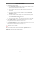
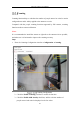
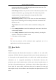
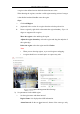
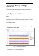
Table Of Contents
- Chapter 1 System Requirement
- Chapter 2 Network Connection
- Chapter 3 Access to the Network Camera
- Chapter 4 Wi-Fi Settings
- Chapter 5 Live View
- Chapter 6 Network Camera Configuration
- Chapter 7 Network Settings
- 7.1 Configuring Basic Settings
- 7.2 Configure Advanced Settings
- 7.2.1 Configuring SNMP Settings
- 7.2.2 Configuring FTP Settings
- 7.2.3 Configuring Email Settings
- 7.2.4 Platform Access
- 7.2.5 Wireless Dial
- 7.2.6 HTTPS Settings
- 7.2.7 Configuring QoS Settings
- 7.2.8 Configuring 802.1X Settings
- 7.2.9 Integration Protocol
- 7.2.10 Bandwidth Adaptation
- 7.2.11 Network Service
- 7.2.12 Smooth Streaming
- Chapter 8 Video/Audio Settings
- Chapter 9 Image Settings
- Chapter 10 Event Settings
- 10.1 Basic Events
- 10.2 Smart Events
- 10.2.1 Configuring Audio Exception Detection
- 10.2.2 Configuring Defocus Detection
- 10.2.3 Configuring Scene Change Detection
- 10.2.4 Configuring Face Detection
- 10.2.5 Configuring Intrusion Detection
- 10.2.6 Configuring Line Crossing Detection
- 10.2.7 Configuring Region Entrance Detection
- 10.2.8 Configuring Region Exiting Detection
- 10.2.9 Configuring Unattended Baggage Detection
- 10.2.10 Configuring Object Removal Detection
- 10.3 VCA Configuration
- Chapter 11 Storage Settings
- Chapter 12 Playback
- Chapter 13 Picture
- Chapter 14 Application
- Appendix

Network Camera User Manual
162
4. Set the detection line.
An orange line, named as detection line can be set on the live video, and the
object entering or exiting through the line will be detected and counted.
1) Click to draw a detection line, and an orange detection line will
appear on the image.
Note:
• The detection line should be drawn at the position right below the
camera, and it should cover the whole entrance / exit.
• Draw the detection line at the position don’t have many people
lingering.
2) Click-and-drag the detection line to adjust its position.
3) Click-and-drag the two end points of the detection line to adjust its length.
4) Click to delete the detection line.
5) Click to to change the direction.
5. Click the button, and the number of the people entered and exited will be
cleared to zero.
6. Click Arming Schedule to enter the arming schedule interface, and
click-and-drag the mouse on the time bar to set the time.
7. Check Linkage Method tab to select the linkage method.
8. Click Save to save the settings.
Note:
The counting statistics will be calculated under Application tab. Go to
Application to check the counting statistics.
Heat Map
Heat map is a graphical representation of data represented by colors. The heat map
function of the camera usually be used to analyze the visit times and dwell time of
customers in a configured area.
Steps:
1. Enter the Heat Map configuration interface: Configuration > Heat Map.