
User's Manual
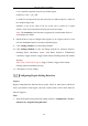
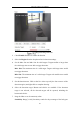
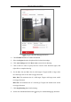
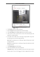
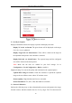
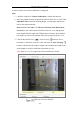
Table Of Contents
- Chapter 1 System Requirement
- Chapter 2 Network Connection
- Chapter 3 Access to the Network Camera
- Chapter 4 Wi-Fi Settings
- Chapter 5 Live View
- Chapter 6 Network Camera Configuration
- Chapter 7 Network Settings
- 7.1 Configuring Basic Settings
- 7.2 Configure Advanced Settings
- 7.2.1 Configuring SNMP Settings
- 7.2.2 Configuring FTP Settings
- 7.2.3 Configuring Email Settings
- 7.2.4 Platform Access
- 7.2.5 Wireless Dial
- 7.2.6 HTTPS Settings
- 7.2.7 Configuring QoS Settings
- 7.2.8 Configuring 802.1X Settings
- 7.2.9 Integration Protocol
- 7.2.10 Bandwidth Adaptation
- 7.2.11 Network Service
- 7.2.12 Smooth Streaming
- Chapter 8 Video/Audio Settings
- Chapter 9 Image Settings
- Chapter 10 Event Settings
- 10.1 Basic Events
- 10.2 Smart Events
- 10.2.1 Configuring Audio Exception Detection
- 10.2.2 Configuring Defocus Detection
- 10.2.3 Configuring Scene Change Detection
- 10.2.4 Configuring Face Detection
- 10.2.5 Configuring Intrusion Detection
- 10.2.6 Configuring Line Crossing Detection
- 10.2.7 Configuring Region Entrance Detection
- 10.2.8 Configuring Region Exiting Detection
- 10.2.9 Configuring Unattended Baggage Detection
- 10.2.10 Configuring Object Removal Detection
- 10.3 VCA Configuration
- Chapter 11 Storage Settings
- Chapter 12 Playback
- Chapter 13 Picture
- Chapter 14 Application
- Appendix

Network Camera User Manual
146
disappears from the region for 10s.
9. Drag the slider to set the sensitivity value.
Sensitivity: Range [1-100]. It stands for the percentage of the body part of an
acceptable target that leaves the pre-defined region.
Sensitivity = 100 – S
1
/S
T
*100
S
1
stands for the target body part that leaves the pre-defined region. S
T
stands for
the complete target body.
Example: if you set the value as 60, a target is possible to be counted as a
removed object only when 40 percent body part of the target leaves the region.
Note: The Sensitivity of the detection is supported by certain models. Refer to
actual display for details.
10. Repeat the above steps to configure other regions. Up to 4 regions can be set. You
can click the Clear button to clear all pre-defined regions.
11. Click Arming Schedule to set the arming schedule.
12. Click Linkage Method to select the linkage methods.
13. Click Save to save the settings.
VCA Configuration
Behavior Analysis
The behavior analysis detects a series of suspicious behavior, and certain linkage
methods will be enabled if the alarm is triggered.