
User's Manual
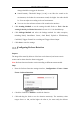
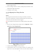
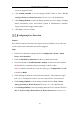
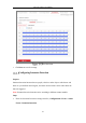
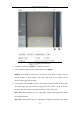
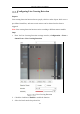
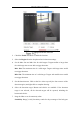
Table Of Contents
- Chapter 1 System Requirement
- Chapter 2 Network Connection
- Chapter 3 Access to the Network Camera
- Chapter 4 Wi-Fi Settings
- Chapter 5 Live View
- Chapter 6 Network Camera Configuration
- Chapter 7 Network Settings
- 7.1 Configuring Basic Settings
- 7.2 Configure Advanced Settings
- 7.2.1 Configuring SNMP Settings
- 7.2.2 Configuring FTP Settings
- 7.2.3 Configuring Email Settings
- 7.2.4 Platform Access
- 7.2.5 Wireless Dial
- 7.2.6 HTTPS Settings
- 7.2.7 Configuring QoS Settings
- 7.2.8 Configuring 802.1X Settings
- 7.2.9 Integration Protocol
- 7.2.10 Bandwidth Adaptation
- 7.2.11 Network Service
- 7.2.12 Smooth Streaming
- Chapter 8 Video/Audio Settings
- Chapter 9 Image Settings
- Chapter 10 Event Settings
- 10.1 Basic Events
- 10.2 Smart Events
- 10.2.1 Configuring Audio Exception Detection
- 10.2.2 Configuring Defocus Detection
- 10.2.3 Configuring Scene Change Detection
- 10.2.4 Configuring Face Detection
- 10.2.5 Configuring Intrusion Detection
- 10.2.6 Configuring Line Crossing Detection
- 10.2.7 Configuring Region Entrance Detection
- 10.2.8 Configuring Region Exiting Detection
- 10.2.9 Configuring Unattended Baggage Detection
- 10.2.10 Configuring Object Removal Detection
- 10.3 VCA Configuration
- Chapter 11 Storage Settings
- Chapter 12 Playback
- Chapter 13 Picture
- Chapter 14 Application
- Appendix

Network Camera User Manual
137
4. Set the Max. Size and Min. Size for valid targets. Targets smaller or larger than
the valid target size are not able to trigger detection.
Max. Size: The maximum size of a valid target. Targets with larger sizes would
not trigger detection.
Min. Size: The minimum size of a valid target. Targets with smaller sizes would
not trigger detection.
5. Set the detection area. Drag the line, and you can locate it on the live video as
desired.
6. Select the detection target. Human and vehicle are available. If the detection
target is not selected, all the detected targets will be reported, including the
human and vehicle.
7. Select the direction for line crossing detection. And you can select the directions
as A<->B, A ->B, and B->A.
A<->B: The object going across the plane with both directions can be detected and
alarms are triggered.
A->B: Only the object crossing the configured line from the A side to the B side
can be detected.
B->A: Only the object crossing the configured line from the B side to the A side
can be detected.
8. Drag the slider to set the sensitivity value.
Sensitivity: Range [1-100]. It stands for the percentage of the body part of an
acceptable target that goes across the pre-defined line.
Sensitivity = 100 – S
1
/S
T
*100
S
1
stands for the target body part that goes across the pre-defined line. S
T
stands
for the complete target body.
Example: if you set the value as 60, the action can be counted as a line crossing
action only when 40 percent or more body part goes across the line.
Note: The Sensitivity of the detection is supported by certain models. Refer to
actual display for details.
9. Repeat the above steps to configure other lines. Up to 4 lines can be set. You can