
User's Manual
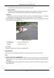
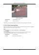
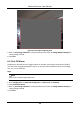
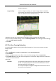
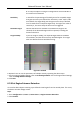
Table Of Contents
- Chapter 1 System Requirement
- Chapter 2 Device Activation and Accessing
- Chapter 3 Live View
- 3.1 Live View Parameters
- 3.1.1 Enable and Disable Live View
- 3.1.2 Adjust Aspect Ratio
- 3.1.3 Live View Stream Type
- 3.1.4 Select the Third-Party Plug-in
- 3.1.5 Light
- 3.1.6 Count Pixel
- 3.1.7 Start Digital Zoom
- 3.1.8 Auxiliary Focus
- 3.1.9 Lens Initialization
- 3.1.10 Quick Set Live View
- 3.1.11 Lens Parameters Adjustment
- 3.1.12 Conduct 3D Positioning
- 3.2 Set Transmission Parameters
- 3.3 Set Smooth Streaming
- 3.1 Live View Parameters
- Chapter 4 Video and Audio
- Chapter 5 Video Recording and Picture Capture
- Chapter 6 Event and Alarm
- 6.1 Basic Event
- 6.2 Smart Event
- 6.2.1 Detect Audio Exception
- 6.2.2 Set Defocus Detection
- 6.2.3 Detect Scene Change
- 6.2.4 Set Face Detection
- 6.2.5 Set Video Loss
- 6.2.6 Set Intrusion Detection
- 6.2.7 Set Line Crossing Detection
- 6.2.8 Set Region Entrance Detection
- 6.2.9 Set Region Exiting Detection
- 6.2.10 Set Unattended Baggage Detection
- 6.2.11 Set Object Removal Detection
- 6.2.12 Draw Area
- 6.2.13 Set Size Filter
- Chapter 7 Network Settings
- Chapter 8 Arming Schedule and Alarm Linkage
- Chapter 9 System and Security
- 9.1 View Device Information
- 9.2 Search and Manage Log
- 9.3 Simultaneous Login
- 9.4 Import and Export Configuration File
- 9.5 Export Diagnose Information
- 9.6 Reboot
- 9.7 Restore and Default
- 9.8 Upgrade
- 9.9 View Open Source Software License
- 9.10 Wiegand
- 9.11 Metadata
- 9.12 Time and Date
- 9.13 Set RS-485
- 9.14 Set RS-232
- 9.15 Power Consumption Mode
- 9.16 External Device
- 9.17 Security
- 9.18 Certificate Management
- 9.19 User and Account
- Chapter 10 Allocate VCA Resource
- Chapter 11 Open Platform
- Chapter 12 Smart Display
- Chapter 13 Set EPTZ
- Chapter 14 Pattern Linkage
- A. Device Command
- B. Device Communication Matrix

Network Camera User Manual
46
B->A: Only the object crossing the configured line from the B side to
the A side can be detected.
Sensitivity
It stands for the percentage of the body part of an acceptable target
that goes across the pre-defined line. Sensitivity = 100 - S1/ST × 100.
S1 stands for the target body part that goes across the pre-defined
line. ST stands for the complete target body. The higher the value of
sensitivity is, the more easily the alarm can be triggered.
Detection Target
Human and vehicle are available. If the detection target is not
selected, all the detected targets will be reported, including the
human and vehicle.
Target Validity
If you set a higher validity, the required target features should be
more obvious, and the alarm accuracy would be higher. The target
with less obvious features would be missing.
Figure 6-5 Set Rule
6. Optional: You can set the parameters of multiple areas by repeating the above steps.
7. For the arming schedule settings, refer to Set Arming Schedule. For the linkage method settings,
refer to Linkage Method Settings.
8. Click Save.
6.2.8 Set Region Entrance Detection
It is used to detect objects entering a pre-defined virtual region from the outside place. If it occurs,
the device can take linkage actions.
Steps
1. Go to Configuration → Event → Smart Event → Region Entrance Detection.
2. Check Enable.