DS-2CCx2D9T-xxxx HD 1080p Ultra Low-Light PoC Camera User Manual
Copyright 2018−2020 Hikvision USA Inc. and Hikvision Canada Inc. Thank you for purchasing our product. If there are any questions, or requests, do not hesitate to contact the dealer. This manual applies to the following HD 1080p Ultra Low-Light PoC cameras: • DS-2CC12D9T-A • DS-2CC12D9T • DS-2CC12D9T-AIT3ZE • DS-2CC52D9T-IT3E • DS-2CC12D9T-E • DS-2CC12D9T-IT5E • DS-2CC52D9T-AVPIT3ZE • DS-2CC12D9T-IT3E • DS-2CC52D9T-AITZE Hikvision USA Inc., 18639 Railroad St.
Manual Illustrations and Features Graphics (screen shots, product pictures, etc.) in this document are for illustrative purposes only. Your actual product may differ in appearance. Your product might not support all features discussed in this document. Trademarks Acknowledgement and other Hikvision trademarks and logos are the properties of Hikvision in various jurisdictions. Other trademarks and logos mentioned below are the properties of their respective owners.
conditions: • • This device may not cause harmful interference. This device must accept any interference received, including interference that may cause undesired operation. EU Conformity Statement This product and, if applicable, the supplied accessories too are marked with “CE” and comply therefore with the applicable harmonized European standards listed under the EMC Directive 2014/30/EU, the LVD Directive 2014/35/EU, the RoHS Directive 2011/65/EU.
Hikvision North America Privacy Policy Last Updated: December 2018 Hikvision USA Inc. and Hikvision Canada Inc. and its affiliates (collectively “HIKVISION”) provide the following services for use in conjunction with various HIKVISION Internetconnected products (“Products”): a HIKVISION user Website and user accounts that may be accessed at us.hikvision.com, ca.hikvision.com, https://distributors-us.hikvision.com/, https://distributors-us.hikvision.com/guestLogin.htm, https://ezviz-rma.hikvision.
your mobile devices, data from cookies, pixel tags, and Web beacons, video content files that do not contain personal visual identity information, the country and time zone of the connected Product, geo-location, mobile phone carrier identification, and device software platform and firmware information.
• use certain non-essential cookies to better understand user behavior, in order to optimize user experience, perfect function design, and offers for products and services from us or to provide better services; • meet a legal obligation, a court order or other binding decision(s); and accomplish a purpose unrelated to those described in this Privacy Policy by first notifying you and, where required, offering you a choice as to whether or not we may use your Personal Information in this different manner.
• We share information to protect our own legitimate business interests when we believe in good faith that we are required or permitted by law to do so. For example, we may share your personal information as needed to support auditing, compliance, and corporate governance functions; to combat fraud or criminal activity; to protect our rights or those of our affiliates and users; or as part of legal proceedings affecting HIKVISION.
If you are located in the European Union, subject to limitations in applicable law, you have certain rights in respect to your personal information such as a right of access, rectification, restriction, opposition, and portability. In order to exercise your rights please contact us at the contact information below in Contact Us. You also have the right to withdraw your consent at all times, free of charge.
Children’s Privacy HIKVISION does not intend that any portion of its HIKVISION Services will be accessed or used by children under the age of 18, or equivalent minimum age in the relevant jurisdiction and such use is prohibited. Our HIKVISION Services are designed and intended for adults.
• • • Canadian Technical Support: techsupport.ca@hikvision.com • HDP partner inquiries (user registration, new partner registration, etc.): partners.usa@hikvision.com • • • • • • • • • US Hikcentral Trial Version Request: sales.usa@hikvision.com Need Help with This Product/Product Detail feature: inside.usa@hikvision.com A&E partner inquiries (user registration, new project support, etc.): aepartners.usa@hikvision.com Canada Hikcentral Trial Version Request: sales.canada@hikvision.
Mandatory Electrical Requirements Hikvision requires the following conditions and equipment for all of its electronic equipment: • Grounding Ensure good conductivity for all ground paths; examine ground path contact surfaces for defects, dirt, corrosion, or nonconductive coatings that may impede conductivity. Repair or clean contact surfaces as necessary to assure good metal-tometal contact. Ensure fasteners are properly installed and tightened. • Electrical Wiring Ensure your outlets are properly wired.
- Maintenance > Replace after a serious electrical event (e.g., lighting blew out a transformer down the street) > Replace yearly in storm-prone areas > Replace every two years as routine maintenance Symbol Conventions The symbols that may be found in this document are defined as follows.
technical specifications for detailed information. • Do not connect several devices to one power adapter as adapter overload may cause overheating or a fire hazard. • Make sure that the plug is firmly connected into the power socket. • If smoke, odor, or noise rise from the device, turn off the power at once, unplug the power cable, and then contact the service center.
Cautions Make sure the power supply voltage is correct before using the camera. Do not drop the camera or subject it to physical shock. Do not touch sensor modules with fingers. If cleaning is necessary, use a clean cloth with a bit of ethanol, and wipe it gently. If the camera will not be used for an extended period, replace the lens cap to protect the sensor from dirt. Do not aim the camera at the sun or extra bright places.
Table of Contents UM DS-2CCx2D9T-xxxx 022520NA (UD02874B-A) 16
UM DS-2CCx2D9T-xxxx 022520NA (UD02874B-A) 17
Introduction 1.1. Product Features The camera is applicable for both indoor and outdoor conditions, and the application scenarios include road, warehouse, underground parking lot, bar, etc.. The main features are as follows: • High performance CMOS sensor • 1080p resolution • Ultra low-light: 0.003 Lux @ (ƒ/1.2, AGC On), 0 Lux with IR • OSD menu, white balance, auto gain, backlight compensation, electronic shutter, etc.
1.2. Overview of Type I Camera Figure 1, Type I Camera 1.3.
1.4. Overview of Type III Camera Figure 3, Type III Camera 1.5. Overview of Type IV Camera Figure 4, Type IV Camera 1.6.
Installation 2.1. Before You Start Make sure that the device in the package is in good condition and all the assembly parts are included. Make sure that all the related equipment is powered off during the installation. Check the specification of the product for the installation environment. Check that the power supply matches your power output to avoid damage. Make sure the wall is strong enough to withstand three times the weight of the camera and the mounting bracket.
Figure 6, Type I Camera Drill Template Figure 7, Type II Camera Drill Template 3. Loosen the screws on the dome camera bubble to remove the bubble and black liner. 4. Attach the of type I camera back box/type II camera base plate to the ceiling and secure with supplied screws.
Figure 8, Attach the Back Box/Base Plate The supplied screw package contains both self-tapping screws and expansion bolts. If the wall is concrete, expansion bolts are required to fix the camera. If the wall is wood, self-tapping screws are required. 5. Route the cables through the cable hole or the side opening. 6. Align the camera with the back box/base plate, and tighten the screws to secure the camera with the back box/base plate.
Figure 9, Affix the Camera to the Ceiling 7. Connect the corresponding cables such as power cable and video cable. 8. Power on the camera to check if the image on the monitor is at an optimum angle. If not, adjust the camera according to the figure below to get an optimum angle. Figure 10, 3-Axis Adjustment 9.
bubble of the dome camera to finish the installation. 2.2.2. Wall Mounting You need to purchase a wall mounting bracket separately if you use wall mounting. 1. Drill four screw holes in the wall according to the bracket holes. 2. Attach the bracket to the wall by aligning the four bracket screw holes with expansion screws on the wall. 3. Secure the bracket with four hex nuts and washers. Figure 11, Install Wall Mounting Bracket 4. Refer to step 3 of 2.1.
Figure 12, Attach Base Plate to Bracket 6. Route the cables through the bracket. 7. Repeat steps 6 to 9 of 2.1.1 Ceiling Mounting to complete the installation. 2.2.3. In-Ceiling Mounting You need to purchase an in-ceiling mounting bracket separately if you use in-ceiling mounting. 1. Attach the drill template on the ceiling. 2. Drill the screw holes and cable holes (optional) in the ceiling according to the supplied drill template. Cable hole is required if routing cable through ceiling outlet. 3.
Figure 13, In-Ceiling Mounting Bracket 5. Route the cables through the cable hole. 6. Attach the type I camera back box/type II camera base plate to the in-ceiling mounting bracket with the supplied screws. The supplied screw package contains both self-tapping screws and expansion bolts. If the wall is concrete, expansion bolts are required to fix the camera. If the wall is wood, self-tapping screws are required. Figure 14, Affix Camera to Mount 7. Repeat steps 6 to 9 of 2.1.
2.2.4. In-Ceiling Mounting with Junction Box You need to purchase an in-ceiling mounting bracket separately if you use in-ceiling mounting with the junction box. Figure 15, Install the Bracket 1. Repeat steps 2 to 4 of the 2.1.3 In-Ceiling Mounting section to secure the in-ceiling mounting bracket (supplied) to the junction box. 2. Connect the corresponding cables such as power cable and video cable. 3.
Figure 16, Affix Camera to Junction Box 4. Repeat steps 6 to 9 of the 2.1.1 Ceiling Mounting section to complete the installation. 2.2.5. Mounting with Inclined Base of Type I Camera You need to purchase an inclined base separately if mounting with an inclined base. 1. Drill four screw holes in the ceiling according to the inclined base holes. 2. Install the inclined base to the ceiling with supplied screws, as shown below.
Figure 17, Affix Inclined Base 3. Route the cables through the inclined base hole. 4. Attach the type I camera back box/type II camera base plate to the inclined base with the supplied screws. Figure 18, Affix Camera to Base 5. Repeat steps 6 to 9 of the 2.1.1 Ceiling Mounting section to complete the installation. 2.3. Type III and Type IV Camera Installation 2.3.1. Ceiling Mounting Both wall mounting and ceiling mounting are suitable for the bullet camera.
example in this section. Use the ceiling mounting steps as a reference for wall mounting. 1. Attach the drill template to the ceiling. 2. Drill the screw holes and cable hole (optional) on the ceiling according to the supplied drill template. Cable hole is required if using ceiling outlet to route the cable. Figure 19, Drill Templates 3. Route the cables through the cable hole. 4. Affix the camera to the ceiling with supplied screws.
Figure 20, Affix Camera to Ceiling 5. Connect the corresponding cables such as power cable and video cable. The supplied screw package contains both self-tapping screws and expansion bolts. If the wall is concrete, expansion bolts are required to affix the camera. If the wall is wood, self-tapping screws are required. 6. Rotate the cover counterclockwise to separate it from the camera to view the auxiliary video output, menu button, and DIP switch shown in figure below. 7.
Figure 21, Internal Interface and Button 8. Power on the camera to check if the image on the monitor is at an optimum angle. If not, adjust the surveillance angle. 1) Loosen the no.1 adjusting screw to adjust the pan position [0° to 360°]. 2) Tighten the no. 1 adjusting screw. 3) Loosen the no. 2 adjusting screw to adjust the tilting position [0° to 90°]. 4) Tighten the no. 2 adjusting screw. 5) Loosen the no. 3 adjusting screw to adjust the rotation position [0° to 360°]. 6) Tighten the no.
Figure 22, 3-Axis Adjustment 2.3.2. Mounting with Junction Box You need to purchase a junction box separately if mounting with a junction box. 1. Attach the drill template to the wall/ceiling. 2. Drill screw holes and cable hole in the wall/ceiling according to the drill template holes. 3. Attach the junction box to the wall/ceiling by aligning the junction box screw holes. 4. Secure the junction box with the PA4 × 25 screws on the wall/ceiling.
Type IIICamera Type IVCamera Figure 23, Install Junction Box 5. Route the cables through the cable hole. 6. Secure the camera with M4 × 10 screws on the junction box. Figure 24, Wall/Ceiling Mounting with Junction Box 7. Repeat steps 5 to 6 of 2.2.1 Ceiling Mounting to install the camera to complete the installation.
2.4. Type V Camera Installation 2.4.1. Ceiling Mounting 1. Disassemble the turret camera by rotating the camera to align the notch to one of the marks, as shown below. Figure 25, Disassemble the Camera 2. Remove the mounting base from the camera body with a flat object, e.g., a coin. 3. Attach the drill template (supplied) where you want to install the camera, and then drill the screw holes and the cable hole (optional) on the ceiling according to the drill template.
Figure 26, Drill Template 4. Attach the mounting base to the ceiling and secure with supplied screws. Figure 27, Attach Mounting Base to Ceiling The supplied screw package contains both self-tapping screws and expansion bolts. If the wall is concrete, expansion bolts are required to affix the camera. If the wall is wood, self-tapping screws are required. 5. Route the cables through the cable hole or the side opening. 6.
Figure 28, Secure Camera with Mounting Base 7. Power on the camera to check that the image on the monitor is at an optimum angle. If not, adjust the camera according to the figure below to get an optimum angle. 1). Hold the camera body and rotate the enclosure to adjust the pan position [0° to 360°]. 2). Move the camera body up and down to adjust the tilt position [0° to 75°]. 3). Rotate the camera body to adjust the rotation position [0° to 360°].
2.4.2. Ceiling Mounting with Junction Box You need to purchase a junction box separately if you use ceiling mounting with a junction box. 1. Disassemble the junction box from the junction box cover. 2. Attach the drill template (supplied) to where you want to fix the junction box, and drill the holes in the ceiling according to the template. Figure 30, Drill Template 3. Affix the junction box body with the supplied screws to the ceiling according to the template. 4.
camera to the junction box. 2.4.3. Wall Mounting You need to purchase a wall mounting bracket separately if you use wall mounting. 1. Drill four screw holes in the wall according to the bracket holes. 2. Attach the bracket to the wall by aligning the bracket’s four screw holes with expansion screws on the wall. 3. Secure the bracket with four hex nuts and washers. Figure 32, Install Wall Mounting Bracket 4. Refer to step 2 of the 2.3.1 Ceiling Mounting section to remove the turret camera’s mounting base.
Figure 33, Attach Mounting Base to Bracket 6. Repeat steps 5 to 7 of the 2.3.1 Ceiling Mounting section to complete the installation. 2.4.4. Mounting with Inclined Base You need to purchase an inclined base separately if you mount with an inclined base. 1. Attach the drill template to the ceiling. 2. Drill screw holes and the cable hole on the ceiling according to the supplied drill template.
Figure 34, Drill Template 3. Disassemble the inclined base with the screwdriver. 4. Install the turret camera’s mounting base to the inclined base cover with three PM4 screws. Figure 35, Install Turret Camera Mounting Base 5. Install the inclined base body to the ceiling with four PA4×25 screws, as shown below.
Figure 36, Affix Inclined Base Body 6. Attach the inclined base cover to its body with supplied screws. 7. Repeat steps 5 to 7 of the 2.3.1 Ceiling Mounting section to complete the installation.
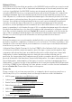
Menu Operation Two methods are available to call the menu. This section takes method b) as an example to start the menu operation. A. Call the menu and adjust the camera parameters with a coaxial camera controller (purchase separately). B. Call the menu with a supported DVR/TVI DVR by clicking the button on the PTZ interface or by calling preset no. 95. Figure 38, Connection 1. After the connection is done, power on the analog camera, DVR/TVI DVR, and the monitor to view the image on the monitor. 2.
Figure 39, Menu Tree UM DS-2CCx2D9T-xxxx 022520NA (UD02874B-A) 45
Camera type IV and type V do not support SMART FOCUS. 3.1. VIDEO OUT • PAL: (Phase Alternating Lines) is a color encoding system for analog television used in broadcast television systems in most countries. • NTSC: (National Television System Committee) is the analog television system that is used in most of North America, parts of South America, Myanmar, South Korea, etc. 3.2. LANGUAGE Supports multiple languages (e.g., English, Japanese, Chinese, etc.) 3.3. SETUP 3.3.1.
• LOW LIGHT: Applicable to environments with low light. Under this circumstance, slow shutter is ON by default to receive more light. 3.3.3. LENS The camera is equipped with a manual lens or a DC (auto iris) lens. Indoor mode and outdoor mode are available for the DC lens. Click IRIS SCAN to initialize the lens. 3.3.4. EXPOSURE Exposure describes the brightness-related parameters. You can adjust the image brightness through the SHUTTER, AGC, SENS-UP, BRIGHTNESS, and D-WDR in different light conditions.
If you select shutter as AUTO or 1/25, SENS-UP is adjustable (OFF/AUTO), and SENS-UP is disabled if any other shutter speed is selected. • AGC: A form of amplification where the camera will automatically boost the image output signal to optimize the image clarity in poor light conditions. You can set the AGC value from 0 to 15. AGC is disabled if the value is set to 0. The noise will be amplified if AGC is on.
weather or in high illumination, in which the dynamic range is lower than that in an ordinary environment, and the image always appears hazy. Enabling Defog can enhance subtle details so that the image appears clearer. Set Defog to ON to enable the function. Position, size, and the defog gradation are configurable. Figure 41, Defog 3.3.5. BACKLIGHT Backlight is applicable for backlighting or a high luminance environment. You can set Backlight to BLC, HSBLC, or WDR.
define the BLC area. - DEFAULT: Restore the BLC settings to the default. Figure 42, BLC • HLC (High Light Compensation): Masks strong light sources that usually flare across a scene. HLC makes it possible to see the image details that would normally be hidden. - GAIN: The HLC gain can be set to High, Middle, or Low. The higher the gain, the clearer the image. - AREA: Click the Up/Down/Left/Right button to define the HLC position and size. Select RET to return to the HLC menu or redefine the BLC area.
Figure 43, HLC • WDR (Wide Dynamic Range): Balances the brightness level of the whole image, and provide the clear image with details. - GAIN: Set the gain of WDR as high, middle, or low. The higher the gain, the clearer the image. - WDR BRIGHT: You can set the value from 0 to 60. The higher the value, the brighter the image is. - WDR OFFSET: You can set the value from 0 to 60.The higher the value, the vaguer the image is.
3.3.6. WHITE BALANCE White balance is the camera’s white rendition function to adjust the color temperature according to the environment. It can remove unrealistic color casts in the image. MANUAL, ATW (Auto-Tracking White Balance), and AWC→SET are selectable. • Manual: Adjusts the white balance by customizing the BLUE and RED value, which range from 1 to 100. • ATW: White balance is continuously adjusted in real time according to the color temperature of the scene illumination.
• D-EFFECT: OFF, MIRROR, V-FLIP, and ROTATE are selectable for the mirror. • OFF: The mirror function is disabled. • MIRROR: The image flips 180 degrees horizontally. • V-FLIP: The image flips 180 degrees vertically. • ROTATE: The image flips 180 degrees both horizontally and vertically. Figure 45, Special • MOTION: In the user-defined motion detection surveillance area, a moving object can be detected, and an alarm will be triggered. 1. Select a motion area. 2. Set the DISPLAY status to ON or OFF. 3.
Figure 46, Motion • PRIVACY: The privacy mask allows you to cover certain areas that you don’t want to be viewed or recorded. Up to eight privacy areas are configurable. Figure 47, Privacy 1. Select a PRIVACY area. 2. Set the DISPLAY status as INV, MOSAIC, COLOR, or OFF. 3. Click Up/Down/Left/Down button to define the position and size of the area. • VOLTAGE DETECTION: Detects if the voltage is over or under normal.
- When the input voltage is 30 percent higher than the calibrated voltage, OVERVOLTAGE flashes on the screen. Camera type IV and type V do not support VOLTAGE DETECTION. • DEFECT: Defective pixels in digital camera CCD or CMOS image sensors fail to sense light levels correctly. This series of camera supports defective pixel correction. Move the cursor to DEFECT and click Iris+ to enter the defective pixel correction interface. LIVE DPC and STATIC DPC are adjustable in this section.
3.3.9. ADJUST In the Adjust sub-menu, you can configure settings including sharpness, image quality on monitor, and LSC (lens shading compensation). Move the cursor to ADJUST and click Iris+ to enter the adjust configuration interface. Figure 49, Adjust • SHARPNESS: Determines the amount of detail an imaging system can reproduce. You can adjust the sharpness from 0 to 15. The higher the value, the clearer and sharper the image. • MONITOR: Monitor CRT and Monitor LCD are selectable.
• LSC (Lens Shading Correction): Corrects the phenomenon that the image is darkened or blurred on the periphery. Set to ON, move the cursor to SCAN, and click Iris+ to correct the lens shading. Set to OFF to disable LSC. 3.3.10. RESET Reset all the settings to the factory default. 3.3.11. EXIT Move the cursor to EXIT and click Iris+ to exit the menu. Using the Video Interference Filter Some dual-voltage Hikvision cameras are susceptible to video signal interference due to AC current spikes.
4.1. Power Filter Use If your video signal displays power line interference (horizontal lines moving across the screen), install the included power filter to eliminate or minimize the interference. Place the power filter between the camera and the leads/ connectors coming out of the power supply. Figure 50, Dual-Voltage Camera Converter/Filter Figure 51, DC Camera Filter • Dual-Voltage Camera Converter/Filter: Flying leads are marked “IN” and “OUT” with yellow flags.
• DC Camera Filter: Has a female barrel connector on the input side and a male barrel connector on the output side; no additional pigtails or other connectors are necessary. The DC power supply has a male pigtail to connect to the camera. Place the filter between the power supply and the camera. Figure 53, DC Filter Installed 4.2. Affected Cameras The following cameras require a (converter)/filter (the model number ending is not specified for all cameras).
UM DS-2CCx2D9T-xxxx 022520NA (UD02874B-A) 60