
User manual
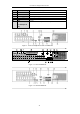
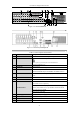
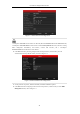

Table Of Contents
- Product Key Features
- Chapter 1 Introduction
- Chapter 2 Getting Started
- Chapter 3 Live View
- Chapter 4 PTZ Controls
- Chapter 5 Recording Settings
- 5.1 Configuring Recording Parameters
- 5.2 Configuring Record Schedule
- 5.3 Configuring Motion Detection Record
- 5.4 Configuring Alarm Triggered Record
- 5.5 Configuring VCA Record
- 5.6 Configuring Manual Record
- 5.7 Configuring Holiday Record
- 5.8 Configuring Redundant Recording
- 5.9 Configuring HDD Group for Recording
- 5.10 Files Protection
- Chapter 6 Playback
- Chapter 7 Backup
- Chapter 8 Alarm Settings
- Chapter 9 Network Settings
- Chapter 10 HDD Management
- Chapter 11 Camera Settings
- Chapter 12 DVR Management and Maintenance
- Chapter 13 Others
- Appendix

User Manual of Digital Video Recorder
31
Figure 1. 16 DS-8132HGHI-SH
Figure 1. 17 DS-8100/9000HQHI-SH
Table 1. 12 Description of Front Panel
No.
Item
Description
1
VIDEO IN
BNC interface for TVI and analog video input.
2
VIDEO OUT
BNC connector for video output.
CVBS output is not provided by DS-7324/7332HGHI-SH and
DS-8124/8132HGHI-SH series.
3
AUDIO IN
RCA connector
4
USB Port
Universal Serial Bus (USB) port for additional devices.
5
HDMI
HDMI video output connector.
DS-8124/8132HGHI-SH provides HDMI1 and HDMI2 interfaces.
6
VGA
DB15 connector for VGA output. Display local video output and
menu.
7
AUDIO OUT
RCA connector.
8
Network Interface
Connector for network
9
RS-485 Interface
Connector for RS-485 devices. T+ and T- pins connect to R+ and R-
pins of PTZ receiver respectively.
D+, D- pin connects to Ta, Tb pin of controller. For cascading
devices, the first DVR’s D+, D- pin should be connected with the
D+, D- pin of the next DVR.
Connector for alarm input.
Connector for alarm output.
10
Power Supply
100 ~ 240V AC power supply.
11
Power Switch
Switch for turning on/off the device.
12
GND
Ground
13
LINE IN
BNC connector for audio input.