IR High-definition Network Speed Dome User Manual UD.
User Manual of Network Speed Dome 1 Thank you for purchasing our product. If there are any questions, or requests, please do not hesitate to contact the dealer. This manual applies to Network Speed Dome. This manual may contain several technical or printing errors, and the content is subject to change without notice. The updates will be added to the new version of this manual. We will readily improve or update the products or procedures described in the manual.
User Manual of Network Speed Dome 2 Regulatory Information FCC Information FCC compliance: This equipment has been tested and found to comply with the limits for a digital device, pursuant to part 15 of the FCC Rules. These limits are designed to provide reasonable protection against harmful interference when the equipment is operated in a commercial environment.
User Manual of Network Speed Dome 3 Safety Instruction These instructions are intended to ensure that the user can use the product correctly to avoid danger or property loss. The precaution measure is divided into ‘Warnings’ and ‘Cautions’: Warnings: Serious injury or death may be caused if any of these warnings are neglected. Cautions: Injury or equipment damage may be caused if any of these cautions are neglected.
User Manual of Network Speed Dome 4 Cautions: Make sure the power supply voltage is correct before using the product. Do not drop the product or subject it to physical shock. Do not install the product on vibratory surface or places. Do not expose it to high electromagnetic radiating environment. Do not aim the lens at the strong light such as sun or incandescent lamp. The strong light can cause fatal damage to the product.
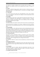
User Manual of Network Speed Dome 5 Table of Contents Chapter 1 Overview.................................................................................................................... 8 1.1 System Requirement........................................................................................................... 8 1.2 Appearance ........................................................................................................................ 8 1.3 Functions.............................
User Manual of Network Speed Dome 6 6.3.1 Configuring TCP/IP Settings ........................................................................................... 44 6.3.2 Configuring Port Settings .............................................................................................. 45 6.3.3 Configuring PPPoE Settings ........................................................................................... 46 6.3.4 Configuring DDNS Settings ................................................
User Manual of Network Speed Dome 10.7 7 RS-485 Settings ............................................................................................................... 100 Appendix ....................................................................................................................................... 101 Appendix 1 SADP Software Introduction ..................................................................................... 101 Appendix 2 Port Mapping ..................................
8 User Manual of Network Speed Dome Chapter 1 Overview 1.1 System Requirement System requirement of web browser accessing is as follows: Operating System: Microsoft Windows XP SP1 and above version / Vista / Win7 / Server 2003 / Server 2008 32bits CPU: Intel Pentium IV 3.0 GHz or higher RAM: 1G or higher Display: 1024×768 resolution or higher Web Browser: Internet Explorer 7.0 and above version, Apple Safari 5.02 and above version, Mozilla Firefox 3.
User Manual of Network Speed Dome 9 This allows for smooth transition from one preset scene to another. It also guarantees that masked area will not be revealed when the dome is moving to a preset. Presets A preset is a predefined image position. When the preset is called, the dome will automatically move to the defined position. The presets can be added, modified, deleted and called.
User Manual of Network Speed Dome 10 If you focus on an object against strong backlight, the object will be too dark to be seen clearly. The BLC (Backlight Compensation) function can compensate light to the object in the front to make it clear, but this causes the over-exposure of the background where the light is strong. Wide Dynamic Range (WDR) The wide dynamic range (WDR) function helps the camera provide clear images even under back light circumstances.
11 User Manual of Network Speed Dome Chapter 2 Network Connection Before you start: If you want to set the network speed dome via a LAN (Local Area Network), please refer to Section 2.1 Setting the Network Speed Dome over the LAN. If you want to set the network speed dome via a WAN (Wide Area Network), please refer to Section 2.2 Setting the Network Speed Dome over the WAN. 2.
12 User Manual of Network Speed Dome Network Cable Speed Dome Switch or Router PC Figure 2-2 Connecting via a Switch or a Router 2.1.2 Detecting and Changing the IP Address You need the IP address to visit the network speed dome. Steps: 1.
13 User Manual of Network Speed Dome Figure 2-3 SADP Interface 2.2 Setting the Network Speed Dome over the WAN Purpose: This section explains how to connect the network speed dome to the WAN with a static IP or a dynamic IP. 2.2.1 Static IP Connection Before you start: Please apply a static IP from an ISP (Internet Service Provider). With the static IP address, you can connect the network speed dome via a router or connect it to the WAN directly.
User Manual of Network Speed Dome 14 Figure 2-4 Accessing the Speed Dome through Router with Static IP Connecting the network speed dome with static IP directly You can also save the static IP in the speed dome and directly connect it to the internet without using a router. Refer to Section 2.1.2 Detecting and Changing the IP Address for detailed IP address configuration of the speed dome. Figure 2-5 Accessing the Speed Dome with Static IP Directly 2.2.
User Manual of Network Speed Dome 15 Connecting the network speed dome via a modem Purpose: This speed dome supports the PPPoE auto dial-up function. The speed dome gets a public IP address by ADSL dial-up after the speed dome is connected to a modem. You need to configure the PPPoE parameters of the network speed dome. Refer to Section 6.3.3 Configuring PPPoE Settings for detailed configuration.
User Manual of Network Speed Dome 16 Figure 2-8 Private Domain Name Resolution Steps: 1. Install and run the IP Server software in a computer with a static IP. 2. Access the network speed dome through the LAN with a web browser or the client software. 3. Enable DDNS and select IP Server as the protocol type. Refer to Section 6.3.4 Configuring DDNS Settings for detailed configuration. © Hikvision Digital Technology Co., Ltd. All Rights Reserved.
17 User Manual of Network Speed Dome Chapter 3 Access to the Network Speed Dome 3.1 Accessing by Web Browsers Steps: 1. Open the web browser. 2. In the address field, input the IP address of the network speed dome, e.g., 192.0.0.64 and press the Enter key to enter the login interface. 3. Select English as the interface language on the top-right of login interface. 4. Input the user name and password and click . Note: The default user name is admin, password is 12345. Figure 3-1 Login Interface 5.
User Manual of Network Speed Dome Figure 3-2 Download and Install Plug-in Figure 3-3 Install Plug-in (1) Figure 3-4 Install Plug-in (2) © Hikvision Digital Technology Co., Ltd. All Rights Reserved.
User Manual of Network Speed Dome 19 Figure 3-5 Install Plug-in (3) Note: You may have to close the web browser to install the plug-in. Please reopen the web browser and log in again after installing the plug-in. 3.2 Accessing by Client Software The product CD contains the client software. You can view the live video and manage the speed dome with the client software. Follow the installation prompts to install the client software and WinPcap.
User Manual of Network Speed Dome 20 Figure 3-7 iVMS-4200 PCNVR Live View Interface Notes: If you use third party VMS software, please contact technical support of our branch for camera firmware. For detailed information about client software of our company, please refer to the user manual of the software. This manual mainly introduces accessing to the network speed dome by web browser. © Hikvision Digital Technology Co., Ltd. All Rights Reserved.
21 User Manual of Network Speed Dome Chapter 4 Live View 4.1 Power-up Action After the power is applied, the speed dome will perform self-test actions. It begins with lens actions and then pan and tilt movement. After the power-up self-test actions, the information as shown in Figure 4-1 will be displayed on screen for 40 seconds. The System Information displayed on the screen includes the dome model, address, protocol, version and other information.
22 User Manual of Network Speed Dome Descriptions of the live view page: Menu Bar Click to show or hide Live View Parameters PTZ control panel PTZ control Live view window Preset/patrol/pattern Toolbar Figure 4-2 Live View Page Menu Bar: Click each tab to enter Live View, Playback, Log and Configuration page respectively. Live View Window: Display the live video. Toolbar: Operations on the live view page, e.g., live view, capture, record, audio on/off, two-way audio, etc.
23 User Manual of Network Speed Dome Figure 4-3 Start Live View Table 4-1 Descriptions of the Toolbar Icon Description Icon Live view on Description Live view off Manually capture the pictures Manual recording off Manual recording on Audio on and adjust volume Mute Two-way audio off Two-way audio on 3D positioning Manual tracking Note: Before using the two-way audio or recording with audio functions, please set the Stream Type to Video & Audio referring to Section 6.4.
24 User Manual of Network Speed Dome the live video. The corresponding position will be moved to the center of the live video and zoomed in. Hold down the left mouse button and drag the mouse to the upper left on the live video. The corresponding position will be moved to the center of the live video and zoomed out. Manual Tracking: Before you start: Please enter the Smart Tracking settings interface and enable smart tracking first. Configuration > Advanced Configuration> PTZ > Smart Tracking Steps: 1.
25 User Manual of Network Speed Dome 4.5.1 PTZ Control Panel On the live view page, click to show the PTZ control panel or click to hide it. Click the direction buttons to control the pan/tilt movements. Click the zoom/iris/focus buttons to realize lens control. Figure 4-4 PTZ Control Panel Table 4-2 Descriptions of PTZ Control Panel Button Description Zoom in/out Focus near/far Iris +/Adjust speed of pan/tilt movements 4.5.
26 User Manual of Network Speed Dome Figure 4-5 Setting a Preset 2. Use the PTZ control buttons to move the lens to the desired position. • Pan the speed dome to the right or left. • Tilt the speed dome up or down. • Zoom in or out. • Refocus the lens. 3. Click to finish the setting of the current preset. 4. You can click to delete the preset. Note: You can configure up to 256 presets. Calling a Preset: In the PTZ control panel, select a defined preset from the list and click preset.
27 User Manual of Network Speed Dome 41 42 43 44 92 Call pattern 1 Call pattern 2 Call pattern 3 Call pattern 4 Start to set limit stops 101 102 103 104 105 Start panorama scan Call patrol 5 Call patrol 6 Call patrol 7 Call patrol 8 Note: You may need to use the OSD(On Screen Display) menu when controlling the speed dome remotely. To display the OSD menu on the live view screen, you can call the preset number 95. 4.5.
User Manual of Network Speed Dome Name Patrol Duration Patrol Speed 5. Click 28 Description It is the duration staying on one patrol point. The speed dome moves to another patrol point after the patrol time. It is the speed of moving from one preset to another. to save a preset into the patrol. 6. Repeat the steps from 3 to 5 to add more presets. 7. Click to save all the patrol settings.
29 User Manual of Network Speed Dome 4.5.4 Setting / Calling a Pattern Purpose: A pattern is a memorized series of pan, tilt, zoom, and preset functions. It can be called on the pattern settings interface. There are up to 4 patterns for customizing. Setting a Pattern: Steps: 1. In the PTZ control panel, click to enter the pattern settings interface. 2. Select a pattern number from the list as shown in Figure 4-9. Figure 4-9 Patterns Settings Interface 3.
30 User Manual of Network Speed Dome Call the current pattern. Stop the current pattern. Delete the current pattern. Notes: These 4 patterns can be operated separately and with no priority level. When configuring and calling the pattern, proportional pan is valid; the limit stops and auto flip will be invalid; and the 3D positioning operation is not supported. 4.6 Configuring Live View Parameters Main stream/Sub-stream/Third stream: You can select , or as the stream type of live viewing.
User Manual of Network Speed Dome 31 Chapter 5 PTZ Configuration 5.1 Configuring Initial Position Purpose: The initial position is the origin of PTZ coordinates. It can be the factory default initial position. You can also customize the initial position according to your own demand. Customize an Initial Position: Steps: 1. Enter the Initial Position Configuration interface: Configuration > Advanced Configuration > PTZ > Initial Position Figure 5-1 PTZ Configuration 2.
User Manual of Network Speed Dome 32 5.2 Configuring Basic PTZ Parameters Purpose: You can configure the basic PTZ parameters, including proportional pan, preset freezing, preset speed, etc. 1. Enter the Basic PTZ Parameter Configuration interface: Configuration > Advanced Configuration > PTZ > Basic Figure 5-2 Basic PTZ Configuration Interface 2.
User Manual of Network Speed Dome 33 Zoom Status: Set the OSD duration of zooming status as 2 seconds, 5 seconds, 10 seconds, Always Close or Always Open. PT Status: Set the azimuth angle display duration while panning and tilting as 2 seconds, 5 seconds, 10 seconds, Always Close or Always Open. Preset Status: Set the preset name display duration while calling the preset as 2 seconds, 5 seconds, 10 seconds, Always Close or Always Open.
User Manual of Network Speed Dome 34 When manual limit stops are set, you can operate the PTZ control panel manually only in the limited surveillance area. Scan Stops: When scan limit stops are set, the random scan, frame scan, auto scan, tilt scan, panorama scan is performed only in the limited surveillance area. Note: Manual Stops of Limit Type is prior to Scan Stops. When you set these two limit types at the same time, Manual Stops is valid and Scan Stops is invalid. 3.
35 User Manual of Network Speed Dome Figure 5-5 Edit the Schedule and Task Type (2) Choose the day you want to set the task schedule. (3) Click All Day to set the schedule as all day; or click Customize and input the Start Time and End Time for each task, and click Enter on your keyboard to enter the time. (4) Choose the task type from the drop-down list. You can choose scan, preset, pattern and etc.
36 User Manual of Network Speed Dome Note: The time of each task can’t be overlapped. Up to 10 tasks can be configured for each day. 5. Click to save the settings. 5.5 Configuring Park Actions Purpose: This feature allows the dome to start a predefined park action (scan, preset, pattern and etc.) automatically after a period of inactivity (park time). Note: Scheduled Tasks function is prior to Park Action function.
37 User Manual of Network Speed Dome 5.6 Configuring Privacy Mask Purpose: Privacy mask enables you to cover certain areas on the live video to prevent certain spots in the surveillance area from being live viewed and recorded. Steps: 1. Enter the Privacy Mask Settings interface: Configuration > Advanced Configuration> PTZ > Privacy Mask Figure 5-9 Draw the Privacy Mask 2. Click the PTZ control buttons to find the area you want to set the privacy mask. 3.
User Manual of Network Speed Dome 38 you can also define the color of the masks. Figure 5-10 Privacy Mask List Figure 5-11 Define Mask Color 7. Check the checkbox of Enable Privacy Mask to enable this function. Note: You are allowed to draw up to 24 areas on the same image. 5.7 Configuring Smart Tracking Purpose: The speed dome tracks the moving objects automatically after you configure this function. Steps: 1.
39 User Manual of Network Speed Dome 2. Check the check box to enable smart tracking function. 3. Click the PTZ buttons to select an object. 4. Click to set the current zoom ratio as the tracking zoom ratio. 5. Set the tracking duration. The speed dome stops tracking when the duration time is up. The duration ranges from 0 to 300 seconds. Notes: Setting the duration to 0 means that there’s no duration when speed dome tracks. Not all the speed dome models support this function.
User Manual of Network Speed Dome 40 Chapter 6 Speed Dome Configuration 6.1 Configuring Local Parameters Note: The local configuration refers to the parameters of the live view and other operations using the web browser. Steps: 1. Enter the Local Configuration interface: Configuration > Local Configuration Figure 6-1 Local Configuration Interface 2. Configure the following settings: Live View Parameters: Set the protocol type, stream type, image size and live view performance.
41 User Manual of Network Speed Dome when using the Multicast function. For other information about Multicast, refer to Section 6.3.1 Configuring TCP/IP Settings. Live View Performance: Set the live view performance to Least Delay, Balanced or Best Fluency. Note: Please set Live View Performance as Best Fluency for the high frame rate speed dome. Rules: You can enable or disable the rules of dynamic analysis for motion here. Record File Settings: Set the saving path of the video files.
42 User Manual of Network Speed Dome Figure 6-2 Time Settings Configuring Time Synchronization by NTP Server (1) Check the checkbox to enable the NTP function. (2) Configure the following settings: Server Address: IP address of NTP server. NTP Port: Port of NTP server, 123 by default. Interval: The time interval between the two synchronizing actions by NTP server. It can be set from 1 to 10080 minutes.
43 User Manual of Network Speed Dome (2) Click to set the system time from the pop-up calendar. (3) Click to save the settings. Note: You can also check the Sync. with computer time checkbox to synchronize the time of the speed dome with the time of your computer. Figure 6-4 Time Sync Manually Select the Time Zone Purpose: When the speed dome is taken to another time zone, you can use the Time Zone function to adjust the time.
44 User Manual of Network Speed Dome Figure 6-6 DST Settings 6.3 Configuring Network Settings 6.3.1 Configuring TCP/IP Settings Purpose: TCP/IP settings must be properly configured before you operate the speed dome over network. IPv4 and IPv6 are both supported. Steps: 1. Enter TCP/IP Settings interface: Configuration > Basic Configuration > Network > TCP/IP Or Configuration > Advanced Configuration > Network > TCP/IP Figure 6-7 TCP/IP Settings © Hikvision Digital Technology Co., Ltd.
45 User Manual of Network Speed Dome 2. Configure the NIC settings, including the IPv4(IPv6) Address, IPv4(IPv6) Subnet Mask and IPv4(IPv6) Default Gateway. 3. Click to save the above settings. Notes: If the DHCP server is available, you can check to automatically obtain an IP address and other network settings from that server. The valid value range of Maximum Transmission Unit(MTU) is 500 ~ 9676. The default value is 1500.
User Manual of Network Speed Dome 2. Set the HTTP port, RTSP port and port of the speed dome. HTTP Port: The default port number is 80. RTSP Port: The default port number is 554. HTTPS Port: The default port number is 443. SDK Port: The default port number is 8000. 3. Click 46 to save the settings. 6.3.3 Configuring PPPoE Settings Purpose: If you have no router but only a modem, you can use Point-to-Point Protocol over Ethernet (PPPoE) function. Steps: 1.
User Manual of Network Speed Dome 47 1. Enter the DDNS Settings interface: Configuration > Advanced Configuration > Network > DDNS Figure 6-11 DDNS Settings 2. Check the Enable DDNS checkbox to enable this feature. 3. Select DDNS Type. Three DDNS types are selectable: IPServer, HiDDNS and DynDNS. DynDNS: Steps: (1) Enter Server Address of DynDNS (e.g. members.dyndns.org). (2) In the Domain text field, enter the domain name obtained from the DynDNS website. (3) Enter the Port of DynDNS server.
User Manual of Network Speed Dome 48 IP Server: Steps: (1) Enter the Server Address of the IP Server. (2) Click to save the settings. Note: The Server Address should be entered with the static IP address of the computer that runs the IP Server software. For the IP Server, you have to apply a static IP, subnet mask, gateway and preferred DNS from the ISP. Figure 6-13 IPServer Settings HiDDNS: Steps: (1) Enter the Server Address: www.hik-online.com. (2) Enter the Domain name of the camera.
49 User Manual of Network Speed Dome 6.3.5 Configuring SNMP Settings Purpose: You can use SNMP to get speed dome status and parameters related information. Before you start: Before setting the SNMP, please use the SNMP software and manage to receive the speed dome information via SNMP port. By setting the Trap Address, the speed dome can send the alarm event and exception messages to the surveillance center. Note: The SNMP version you select should be the same as that of the SNMP software. Steps: 1.
50 User Manual of Network Speed Dome , ) to enable the feature. 3. Configure the SNMP settings. Note: The configuration of the SNMP software should be the same as the settings you configure here. 4. Click to save and finish the settings. 6.3.6 Configuring 802.1X Settings Purpose: The speed dome supports IEEE 802.1X standard. IEEE 802.1X is a port-based network access control. It enhances the security level of the LAN. When devices connect to this network with IEEE 802.
User Manual of Network Speed Dome 51 camera. If all the information is validated, the switch allows the network access to the protected network. Steps: 1. Connect the network camera to your PC directly with a network cable. 2. Enter the 802.1X Settings interface: Configuration > Advanced Configuration > Network > 802.1X Figure 6-17 802.1X Settings 3. 4. 5. Check the Enable IEEE 802.1X checkbox to enable it. Configure the 802.1X settings, including user name and password.
52 User Manual of Network Speed Dome Figure 6-18 QoS Settings 2. Configure the QoS settings, including video/audio DSCP, event/alarm DSCP and Management DSCP. The valid DSCP value ranges from 0 to 63. The DSCP value is bigger, the priority is higher. 3. Click to save the settings. Notes: Make sure that you enable the QoS function of your network device (such as a router). It will ask for a reboot for the settings to take effect. 6.3.
User Manual of Network Speed Dome 2. 53 Configure the FTP settings, including server address, port, user name, password, directory and upload type. Setting the directory in FTP server for saving files: In the Directory Structure field, you can select the root directory, parent directory and child directory. Root directory: The files will be saved in the root of FTP server. Parent directory: The files will be saved in a folder in FTP server.
User Manual of Network Speed Dome 54 Figure 6-22 Configure UPnP Settings 4. Click to save the settings. Port Maping Steps: 1. Check the Enable Port Mapping checkbox 2. Select the Port Mapping Mode as Auto or Manual. 3. If in Manual mode, you can check the checkbox of HTTP, RTSP or SDK port according to your demand. 4. Click to save the settings. 6.3.
User Manual of Network Speed Dome 55 Figure 6-23 Email Settings 2. Configure the following settings: Sender: The name of the email sender. Sender’s Address: The email address of the sender. SMTP Server: The SMTP Server IP address or host name (e.g., smtp.263xmail.com). SMTP Port: The SMTP port. The default TCP/IP port for SMTP is 25. Enable SSL: Check the checkbox to enable SSL if it is required by the SMTP server.
User Manual of Network Speed Dome 56 Authentication (optional): If your email server requires authentication, check this checkbox to use authentication to log in to this server and enter the login user name and password. Receiver: Select the receiver to which the email is sent. Up to 2 receivers can be configured. Receiver: The name of the user to be notified. Receiver’s Address: The email address of user to be notified. 3. Click to save the settings. 6.4 Configuring Video and Audio Settings 6.4.
User Manual of Network Speed Dome 57 sub-stream: Video Type: Select the stream type to video stream, or video & audio composite stream. The audio signal will be recorded only when the Video Type is Video & Audio. Resolution: Select the resolution of the video output. Bitrate Type: Select the bitrate type to constant or variable. Video Quality: When bitrate type is selected as Variable, 6 levels of video quality are selectable.
User Manual of Network Speed Dome 58 Audio Encoding: G.711ulaw, G.711alaw and G.726 selectable. 3. Click to save the settings. 6.4.3 Configuring ROI Settings Before you start: ROI (Region of Interest) encoding is used to enhance the quality of images which are specified in advance. Stream Type: You can set the ROI function for main stream, sub stream or third stream. Select a stream type and then configure the ROI settings. Fixed Region: Draw several fixed areas and apply the ROI function on them.
User Manual of Network Speed Dome 59 Figure 6-26 Region of Interest Dynamic Tracking: The center area of the tracking scene is specified ROI function by default. When the speed dome starts smart tracking, the quality in the image center is enhanced. Steps: 1. Check the check box of Enable under Dynamic Tracking. 2. Adjust the Enhance the level from 1 to 6. The higher the value, the better the ROI quality. 3. Click Save to save the settings. 6.5 Configuring Image Settings 6.5.
User Manual of Network Speed Dome 60 Notes: The parameters in Display Settings interface vary depending on the models of speed dome. You can double click the live view to enter full screen mode and double click it again to exit. Steps: 1. Enter the Display Settings interface: Configuration > Basic Configuration> Image> Display Settings Or Configuration > Advanced Configuration> Image> Display Settings 2. Set the image parameters of the speed dome.
61 User Manual of Network Speed Dome Brightness This feature is used to adjust brightness of the image. The value ranges from 0 to 100. Contrast This feature enhances the difference in color and light between parts of an image. The value ranges from 0 to 100. Saturation This feature is used to adjust color saturation of the image. The value ranges from 0 to 100. Limit Gain This feature is used to adjust gain of the image. The value ranges from 0 to 100.
62 User Manual of Network Speed Dome Exposure Mode The Exposure Mode can be set to Auto, Iris Priority, Shutter Priority, Manual. Auto: The iris, shutter and gain values will be adjusted automatically according to the brightness of the environment. Iris Priority: The value of iris needs to be adjusted manually. The shutter and gain values will be adjusted automatically according to the brightness of the environment.
63 User Manual of Network Speed Dome Auto: In Auto mode, the day mode and night mode can switch automatically according to the light condition of environment. The switching sensitivity can be set to Low, Normal, High. Figure 6-31 Auto Mode Sensitivity Day: In Day mode, the speed dome displays color image. It is used for normal lighting conditions. Night: In Night mode, the image is black and white. Night mode can increase the sensitivity in low light conditions.
64 User Manual of Network Speed Dome Note: This function varies depending on the models of speed dome. Slow Shutter This function can be used in underexposure condition. It lengthens the shutter time to ensure full exposure. The slow shutter value can be set to Low, Normal and High. Figure 6-33 Slow Shutter Lens Initialization The lens operates the movements for initialization when you check the check box of Lens Initialization.
User Manual of Network Speed Dome 65 Sodium Lamp You can select this mode when there are sodium lamps installed near the speed dome. Auto-Track In Auto-Track mode, white balance is continuously being adjusted in real-time according to the color temperature of the scene illumination. Note: This function varies depending on the models of speed dome. 3D Digital Noise Reduction You can enable or disable the 3D Digital Noise Reduction function as shown in Figure 6-35. The level ranges from 0 to 100.
User Manual of Network Speed Dome 66 Figure 6-36 Chroma Suppress Note: This function varies depending on the models of speed dome. HLC HLC (High Light Compensation) makes the camera identify and suppress the strong light sources that usually flare across a scene. This makes it possible to see the detail of the image that would normally be hidden. Local Output You can select the output mode to ON or OFF. 6.5.
67 User Manual of Network Speed Dome Figure 6-37 OSD Settings 2. Check the corresponding checkbox to select the display of speed dome name, date or week if required. 3. Edit the speed dome name in the text field of Camera Name. 4. Select from the drop-down list to set the time format, date format and display mode. 5. You can use the mouse to click and drag the text frame view window to adjust the OSD position. Figure 6-38 Adjust OSD Location © Hikvision Digital Technology Co., Ltd. All Rights Reserved.
68 User Manual of Network Speed Dome 6. Click to activate above settings. 6.5.3 Configuring Text Overlay Settings Purpose: You can customize the text overlay. Steps: 1. Enter the Text Overlay Settings interface: Configuration > Advanced Configuration > Image > Text Overlay 2. Check the checkbox in front of textbox to enable the on-screen display. 3. Input the characters in the textbox. 4. Use the mouse to click and drag the red text frame in the live view window to adjust the text overlay position. 5.
User Manual of Network Speed Dome 69 and exception. These events can trigger the alarm actions, such as Notify Surveillance Center, Send Email, Trigger Alarm Output, etc. For example, when an external alarm is triggered, the network speed dome sends a notification to an e-mail address. 6.6.1 Configuring Motion Detection Purpose: Motion detection is a feature which can trigger alarm actions and actions of recording videos when the motion occurred in the surveillance scene. Steps: 1.
70 User Manual of Network Speed Dome (4) Click to finish drawing. Note: You can click 2. to clear all of the areas. (5) Move the slider detection. Set the Arming Schedule for Motion Detection. Steps: to set the sensitivity of the (1) To edit the arming schedule as shown in Figure 6-42, click in Figure 6-41. Figure 6-41 Arming Schedule (2) Choose the day you want to set the arming schedule as shown in Figure 6-42. (3) Click to set the time period for the arming schedule.
User Manual of Network Speed Dome 71 Figure 6-42 Arming Time Schedule 3. Set the Alarm Actions for Motion Detection. Purpose: You can specify the linkage method when an event occurs. The following contents are about how to configure the different types of linkage method. Figure 6-43 Linkage Method Check the checkbox to select the linkage method. Notify surveillance center, send email, upload to FTP, trigger channel and trigger alarm output are selectable.
72 User Manual of Network Speed Dome 6.3.10 Configuring Email Settings to set the Email parameters. Upload to FTP Capture the image when an alarm is triggered and upload the picture to a FTP server. Note: You need a FTP server and set FTP parameters first. Refer to Section 6.3.8 Configuring FTP Settings for setting FTP parameters. Trigger Channel Record a video when an event occurs. Note: You have to set the recording schedule to realize this function. Please refer to Section 7.
User Manual of Network Speed Dome 73 2. Check the Enable Video Loss Detection checkbox to enable the video loss detection. 3. Click to edit the arming schedule for video loss detection. The arming schedule configuration is the same as the setting of the arming schedule for motion detection. Refer to Step 2 Set the Arming Schedule for Motion Detection in Section 6.6.1. 4. Check the checkbox to select the linkage method taken for the video loss alarm.
User Manual of Network Speed Dome 74 3. Set the tamper-proof area. Refer to Step 1 Set the Motion Detection Area in Section 6.6.1 Configuring Motion Detection. 4. Click to edit the arming schedule for tamper-proof. The arming schedule configuration is the same as the setting of the arming schedule for motion detection. Refer to Step 2 Set the Arming Schedule for Motion Detection in Section 6.6.1 Configuring Motion Detection. 5. Check the checkbox to select the linkage method taken for the tamper-proof.
User Manual of Network Speed Dome 75 Figure 6-46 Alarm Input Settings 4. Click to set the arming schedule for the alarm input. Refer to Step 2 7. Set the Arming Schedule for Motion Detection in Section 6.6.1 Configuring Motion Detection. Check the checkbox to select the linkage method taken for the alarm input. Refer to Step 3 Set the Alarm Actions for Motion Detection in Section 6.6.1 Configuring Motion Detection. You can also choose the PTZ linking for the alarm input.
User Manual of Network Speed Dome 76 Figure 6-47 Linkage Method 6.6.5 Configuring Alarm Output Steps: 1. Enter the Alarm Output Settings interface: Configuration>Advanced Configuration> Events > Alarm Output 2. Select one alarm output channel in the Alarm Output drop-down list. 3. 4. Set a name in for the alarm output (optional). The Delay time can be set to 5sec, 10sec, 30sec, 1min, 2min, 5min, 10min or Manual.
User Manual of Network Speed Dome 77 Figure 6-48 Alarm Output Settings 6.6.6 Handling Exception The exception type can be HDD full, HDD error, network disconnected, IP address conflicted and illegal login to the speed domes. Steps: 1. Enter the Exception Settings interface: Configuration > Advanced Configuration> Events > Exception 2. Check the checkbox to set the actions taken for the Exception alarm. Refer to Step 3 Set the Alarm Actions Taken for Motion Detection in Section 6.6.
User Manual of Network Speed Dome Figure 6-49 Exception Settings 3. Click to save the settings. © Hikvision Digital Technology Co., Ltd. All Rights Reserved.
User Manual of Network Speed Dome 79 Chapter 7 Record Settings Before you start: To configure record settings, please make sure that you have the network storage device within the network or the SD card inserted in your speed dome. 7.1 Configuring NAS Settings Before you start: The network disk should be available within the network and properly configured to store the recorded files, log files, etc. Steps: 1.
80 User Manual of Network Speed Dome Figure 7-2 Initialize Disk Figure 7-3 Initializing When the initialization completed, the status of disk will become Normal as shown in Figure 7-4. Figure 7-4 View Disk Status Notes: Up to 8 NAS disks can be connected to the speed dome. To initialize and use the SD card after insert it to the speed dome, please refer to the steps of NAS disk initialization. 7.
User Manual of Network Speed Dome 81 Figure 7-5 Recording Schedule Interface 2. Check the checkbox of Enable Record Schedule to enable scheduled recording. 3. Set the record parameters of the speed dome. Figure 7-6 Record Parameters Pre-record: The time you set to start recording before the scheduled time or the event. For example, if an alarm triggers recording at 10:00, and the pre-record time is set as 5 seconds, the speed dome starts to record at 9:59:55.
User Manual of Network Speed Dome 82 dome model. 4. Click to edit the record schedule. Figure 7-7 Record Schedule 5. Choose the day to set the record schedule. (1) Set all-day record or segment record: If you want to configure the all-day recording, please check the All Day checkbox. If you want to record in different time sections, check the Customize checkbox. Set the Start Time and End Time. Note: The time of each segment can’t be overlapped. Up to 4 segments can be configured.
83 User Manual of Network Speed Dome 6.6.1 Configuring Motion Detection. Record Triggered by Alarm If you select Alarm, the video will be recorded when the alarm is triggered via the external alarm input channels. Besides configuring the recording schedule, you have to set the Alarm Type and check the checkbox of Trigger Channel in the Linkage Method of Alarm Input Settings interface. For detailed information, please refer to Section 6.6.4 Configuring External Alarm Input.
84 User Manual of Network Speed Dome date and click (4) Click . to save the settings and exit the Edit Record Schedule interface. 6. Click to save the settings. 7.3 Configuring Snapshot Settings Purpose: You can configure the scheduled snapshot and event-triggered snapshot. You can upload the captured pictures to a FTP server. Basic Settings Steps: 1. Enter the Snapshot Settings interface: Configuration > Advanced Configuration > Storage > Snapshot 2.
85 User Manual of Network Speed Dome 1) Configure the FTP settings and check checkbox in FTP Settings interface. Please refer to Section 6.3.8 Configuring FTP Settings for more details to configure FTP parameters. 2) Check checkbox in Motion Detection Settings or Alarm Input interface. Please refer to Step 3 Set the Alarm Actions Taken for Motion Detection in Section 6.6.1 Configuring Motion Detection, or Step 4 Configuring External Alarm Input in Section 6.6.1 Configuring Motion Detection.
86 User Manual of Network Speed Dome Chapter 8 Playback Purpose: This section explains how to view the remotely recorded video files stored in the network disks or SD cards. Task 1: To play back the video files Steps: 1. Click on the menu bar to enter playback interface. Figure 8-1 Playback Interface 2. Select the date and click . Figure 8-2 Search Video © Hikvision Digital Technology Co., Ltd. All Rights Reserved.
87 User Manual of Network Speed Dome 3. Click to play the video files found on this date. The toolbar on the bottom of Playback interface can be used to control playing process.
88 User Manual of Network Speed Dome types as shown in Figure 8-6. Figure 8-6 Video Types Task 2: To download the video files Steps: 1. Click on the playback interface. The pop-up menu is shown in Figure 8-7. 2. Set the start time and end time. Click Search. The corresponding video files are listed on the left. Figure 8-7 Video Downloading interface 3. Check the checkbox 4. Click in front of the video files that you need to download. to download the video files.
89 User Manual of Network Speed Dome 2. 3. Set the linkage type of capturing the pictures as timing, alarm, motion, etc.. Set the start time and end time. Click Search. The corresponding picture files are listed on the left. 4. Check the checkbox 5. Click in front of the files that you need to download. to download the files. Figure 8-8 Picture Downloading interface © Hikvision Digital Technology Co., Ltd. All Rights Reserved.
90 User Manual of Network Speed Dome Chapter 9 Log Searching Purpose: The operation, alarm, exception and information of the speed dome can be stored in log files. You can also export the log files on your demand. Before you start: Please configure network storage for the speed dome or insert a SD card in the speed dome. Steps: 1. Click on the menu bar to enter log searching interface. Figure 9-1 Log Searching Interface 2.
91 User Manual of Network Speed Dome 4. To export the log files, click to save the log files in your computer. © Hikvision Digital Technology Co., Ltd. All Rights Reserved.
User Manual of Network Speed Dome 92 Chapter 10 Others 10.1 Managing User Accounts Enter the User Management interface: Configuration >Basic Configuration> Security > User Or Configuration > Advanced Configuration> Security > User The admin user has access to create, modify or delete other accounts. Up to 32 user accounts can be created. Figure 10-1 User Information Add a User Steps: 1. Click to add a user. 2. Input the new User Name, select Level and input Password.
93 User Manual of Network Speed Dome Figure 10-2 Add a User Modify a User Steps: 1. Left-click to select the user from the list and click . 2. Modify the User Name, Level or Password. 3. In the Basic Permission field and Camera Configuration field, you can check or uncheck the permissions. 4. Click to finish the user modification. © Hikvision Digital Technology Co., Ltd. All Rights Reserved.
94 User Manual of Network Speed Dome Figure 10-3 Modify a User Delete a User Steps: 1. Left-click the user name you want to delete and click 2. Click . on the pop-up dialogue box to delete the user. Figure 10-4 Delete a User © Hikvision Digital Technology Co., Ltd. All Rights Reserved.
User Manual of Network Speed Dome 95 10.2 Configuring RTSP Authentication Purpose: You can specifically secure the stream data of live view. Steps: 1. Enter the RTSP Authentication interface: Configuration> Advanced Configuration> Security > RTSP Authentication Figure 10-5 RTSP Authentication 2. Select the Authentication type basic or disable in the drop-down list to enable or disable the RTSP authentication. 3. Click to save the settings. 10.
User Manual of Network Speed Dome 96 10.4 Configuring IP Address Filter With this function on, the camera allows certain IP addresses whether to log in or not. Filter Type Description Forbid the IP addresses added in Forbidden the IP Address Filter interface to log in. Allow only the IP addresses Allowed added in the IP Address Filter interface to log in. Figure 10-8 IP Address Filter 10.
User Manual of Network Speed Dome Figure 10-9 Device Information 10.6 Maintenance 10.6.1 Rebooting the Speed Dome Steps: 1. Enter the Maintenance interface: Configuration > Basic Configuration> System > Maintenance Or Configuration > Advanced Configuration> System > Maintenance: 2. Click to reboot the network speed dome. Figure 10-10 Reboot the Device 10.6.2 Restoring Default Settings Steps: 1.
98 User Manual of Network Speed Dome 2. Click Note: Clicking or to restore the default settings. restores all the parameters to default settings including the IP address and user information. Please use this button with caution. Figure 10-11 Restore Default Settings 10.6.3 Importing/Exporting Configuration File Steps: 1. Enter the Maintenance interface: Configuration > Basic Configuration> System > Maintenance Or Configuration > Advanced Configuration> System > Maintenance 2.
User Manual of Network Speed Dome 2. Click 99 to select the local upgrade file and then click to start remote upgrade. Note: The upgrading process will take 1 to 10 minutes. Please don't disconnect power of the speed dome during the process. The speed dome reboots automatically after upgrading. Figure 10-13 Remote Upgrade © Hikvision Digital Technology Co., Ltd. All Rights Reserved.
100 User Manual of Network Speed Dome 10.7 RS-485 Settings Purpose: The RS-485 serial port is used to control the PTZ of the camera. The configuring of the PTZ parameters should be done before you control the PTZ unit. Steps: 1. Enter RS-485 parameter setting interface: Configuration> Advanced Configuration> System > RS485 Figure 10-14 RS-485 Settings 2. Set the RS-485 parameters and click to save the settings.
101 User Manual of Network Speed Dome Appendix Appendix 1 SADP Software Introduction Description of SADP SADP (Search Active Devices Protocol) is a kind of user-friendly and installation-free online device search tool. It searches the active online devices within your subnet and displays the information of the devices. You can also modify the basic network information of the devices using this software.
102 User Manual of Network Speed Dome information; you can click to expand the device table and hide the network parameter panel on the right side, or click to show the network parameter panel. Modify network parameters Steps: 1. Select the device to be modified in the device list and the network parameters of the device will be displayed in the Modify Network Parameters panel on the right side. 2. Edit the modifiable network parameters, e.g. IP address and port number. 3.
User Manual of Network Speed Dome 103 Appendix 2 Port Mapping The following settings are for TP-LINK router (TL-R410). The settings vary depending on different models of routers. Steps: 1. Select the WAN Connection Type, as shown below: Figure A.2.1 Select the WAN Connection Type 2. Set the LAN parameters of the router as in the following figure, including IP address and subnet mask settings. Figure A.2.2 Set the LAN parameters 3. Set the port mapping in the virtual severs of Forwarding.
104 User Manual of Network Speed Dome Example: When the speed domes are connected to the same router, you can forward the ports of a speed dome as 80, 8000, 8200~8210 and 554 with IP address 192.168.1.23, and the ports of another speed dome as 81, 8001, 8201~8211 and 555 with IP 192.168.1.24. Refer to the steps as below: Steps: 1. As the settings mentioned above, forward the port 80, 8000, 8200~8210 and 554 for the network speed dome at 192.168.1.23 2.