E-series HD Camera User Manual UD.
E-series High-definition Camera·User Manual Thank you for purchasing our product. If there are any questions, or requests, please do not hesitate to contact the dealer.
E-series High-definition Camera·User Manual Regulatory Information FCC Information FCC compliance: This equipment has been tested and found to comply with the limits for a digital device, pursuant to part 15 of the FCC Rules. These limits are designed to provide reasonable protection against harmful interference when the equipment is operated in a commercial environment.
E-series High-definition Camera·User Manual For more information see: www.recyclethis.info. 2006/66/EC (battery directive): This product contains a battery that cannot be disposed of as unsorted municipal waste in the European Union. See the product documentation for specific battery information. The battery is marked with this symbol, which may include lettering to indicate cadmium (Cd), lead (Pb), or mercury (Hg).
E-series High-definition Camera·User Manual Safety Instruction These instructions are intended to ensure that user can use the product correctly to avoid danger or property loss. The precaution measure is divided into Warnings and Cautions. Warnings: Serious injury or death may occur if any of the warnings are neglected. Cautions: Injury or equipment damage may occur if any of the cautions are neglected.
E-series High-definition Camera·User Manual This installation should be made by a qualified service person and should conform to all local codes. Please install blackouts equipment into the power supply circuit for convenient supply interruption. Please make sure that the ceiling can support more than 50(N) Newton gravities if the camera is fixed to the ceiling. Cautions Make sure the power supply voltage is correct before using the camera.
E-series High-definition Camera·User Manual While shipping, the camera should be packed in its original packing, or packing of the same texture. Improper use or replacement of the battery may result in hazard of explosion. Replace with the same or equivalent type only. Dispose of used batteries according to the instructions provided by the battery manufacturer.
E-series High-definition Camera·User Manual Table of Contents 1 Introduction ........................................................................ 8 1.1 Product Features ........................................................8 1.2 Appearance of Camera ..................................................9 2 Installation ....................................................................... 12 2.1 Installation of DS-2CE5512P(N) and DS-2CE5582P(N) Dome Camera ...............................................
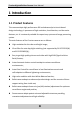
E-series High-definition Camera·User Manual 1 Introduction 1.1 Product Features This camera adopts high performance DIS and advanced print circuit board design technology. It possesses of high resolution, low distortion, and low noise features, etc. It is extremely suitable for supervisory system and image processing system. The main features of the E-series cameras are as follows.
E-series High-definition Camera·User Manual 1.
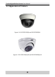
E-series High-definition Camera·User Manual Figure 1-3 DS-2CE5512P(N)-IRP and DS-2CE5582P(N)-IRP Figure 1-4 DS-2CE1512P(N)-IR and DS-2CE1582P(N)-IR Figure 1-5 DS-2CE1582P(N)-IR1(IR3) 10
E-series High-definition Camera·User Manual Figure 1-6 DS-2CE5582P(N)-IR1(IR3) 11
E-series High-definition Camera·User Manual 2 Installation Before you start: When mounting the camera, for the cement wall, you need to mount the base with expansion screws. For the wooden wall, you need to mount the base with self-tapping screws. Please ensure that the wall is strong enough to withstand more than 3 times the weight of the camera and the bracket. If the wall is not strong enough, the camera may fall and cause serious damage.
E-series High-definition Camera·User Manual Steps: 1. Rotate the bubble counterclockwise and remove it. Figure 2-2 Remove the Bubble 2. Drill the holes on the wall with the supplied drilling template. 3. Route the cables inside the ceiling or on the surface. If you want to route the cables inside the ceiling, drill the cable hole in the ceiling for wiring; pull all cables through the hole and terminate all wires (if not already terminated). 4.
E-series High-definition Camera·User Manual 5. Three-axis adjustment. 1) Preview the image of the camera on a monitor. 2) Rotate the panning table to adjust the panning position of the camera. The adjusting range is from 0 degree to 355 degrees. 3) Loosen the tilting lock screw. 4) Rotate the tilting table to adjust the tilting position of the camera. The adjusting range is from 0 degree to 90 degrees. 5) Tighten the tilting lock screw.
E-series High-definition Camera·User Manual Figure 2-5 Reinstall the Bubble Figure 2-6 Finish the Installation Installation with junction box: Steps: 1.
E-series High-definition Camera·User Manual Figure 2-7 Remove the Bubble 2. Secure the DS-1244ZJ (not supplied) to the single gang box with screws. Single gang box DS-1244ZJ Figure 2-8 Secure the DS-1244ZJ 3. Route the cables inside the ceiling or on the surface. If you want to route the cables inside the ceiling, drill the cable hole in the ceiling for wiring; pull all cables through the hole and terminate all wires (if not already terminated). 4.
E-series High-definition Camera·User Manual Figure 2-9 Secure the Back Box 5. Three-axis adjustment. 6. Rotate the bubble clockwise to reinstall it to the dome camera.
E-series High-definition Camera·User Manual Figure 2-11 Finish the Installation 2.2 Installation of DS-2CE5512P(N)-IR and DS-2CE5582P(N)-IR Dome Camera Power cable Video cable Mounting base Enclosure Dome Figure 2-12 Overview Steps: 1. Loosen the screws on the dome to remove the enclosure.
E-series High-definition Camera·User Manual Figure 2-13 Remove the Enclosure 2. Drill the holes on the wall with the supplied drilling template. 3. Route the cables inside the ceiling or on the surface. If you want to route the cables inside the ceiling, drill the cable hole in the ceiling for wiring; pull all cables through the hole and terminate all wires (if not already terminated). 4. Secure the mounting base of dome camera to the ceiling with the screws.
E-series High-definition Camera·User Manual 5. Connect the video cable and power cable and install the dome and the enclosure to match the mounting base and fasten the set screw slightly but not tightly, so that you can make adjustments to the camera and lens. Figure 2-15 Install the Enclosure and Dome 6. Preview the image of the camera on a monitor and adjust the lens to the optimum angle and fasten the set screw tightly. Note: The adjustable tilt angle range is 0 ° ~ 75 °.
E-series High-definition Camera·User Manual 2.3 Installation of DS-2CE5512P(N)-IRP and DS-2CE5582P(N)-IRP Dome Camera Power cable Video cable Mounting base Mounting base cover Dome module Figure 2-17 Overview Steps: 1. Remove the dome module from the mounting base. Figure 2-18 Remove the Dome Module 2. Drill the holes on the wall with the supplied drilling template. 3. Attach the mounting base to the ceiling and secure it with screws.
E-series High-definition Camera·User Manual Figure 2-19 Mount the Mounting Base 4. Route the cables inside the ceiling or on the surface. If you want to route the cables inside the ceiling, drill the cable hole in the ceiling for wiring; pull all cables through the hole and terminate all wires (if not already terminated). 5. Connect the video cable and power cable and push the camera module to the mounting base until it is fixed.
E-series High-definition Camera·User Manual 6. Attach the mounting base cover to the mounting base and rotate it slightly but not tightly, so that you can make adjustments to the camera and lens. Rotate clockwise Figure 2-21 Attach the Mounting Base Cover 7. Three-axis adjustment. 1). Preview the image of the camera on a monitor. 2). Rotate the panning table to adjust the panning position of the camera. The adjusting range is from 0 degree to 360 degrees. 3). Loosen the tilting lock screw. 4).
E-series High-definition Camera·User Manual Pan Rotation Tilt Figure 2-22 Adjust the lens 8. Tighten the mounting base cover again tightly to secure the dome camera.
E-series High-definition Camera·User Manual 2.4 Installation of DS-2CE1512P(N)-IR and DS-2CE1582P(N)-IR Bullet Camera Power cable Video cable Mounting base Figure 2-24 Overview Steps: 1. Place the drill template on the wall/ceiling and mark screw positions. 2. Route the cables inside the ceiling or on the surface.
E-series High-definition Camera·User Manual Ceiling Figure 2-25 Bullet Camera Installation 4. Three-axis adjustment. 1). Preview the image of the camera on a monitor. Note: You must loosen the lock screw before adjustment and tighten it when you adjusted it. 2). Rotate the panning axis to adjust the panning position of the camera. The adjustable range is from 0 degree to 360 degrees. 3). Rotate the tilting axis to adjust the tilting position of the camera.
E-series High-definition Camera·User Manual Pan: 0°~360° Lock screw Tilt: 0°~90° Rotation: 0°~360° Figure 2-26 3-axis Adjustment 2.5 Installation of DS-2CE1582P(N)-IR1(IR3) Bullet Camera Power cable Video cable Mounting base Figure 2-27 Overview Steps: 1. Drill the holes on the wall with the supplied drilling template.
E-series High-definition Camera·User Manual 2. Route the cables inside the ceiling or on the surface. If you want to route the cables inside the ceiling, drill the cable hole in the ceiling for wiring; pull all cables through the hole and terminate all wires (if not already terminated). 3. Connect the video cable and power cable and secure the mounting base with camera to the wall with supplied screws. Figure 2-28 Secure the Camera 4. Three-axis adjustment. 1).
E-series High-definition Camera·User Manual Pan: 0°~360° Lock screw-1 Tilt: 0°~90° Lock screw-2 Figure 2-29 3-axis Adjustment 5. Rotation: 0°~360° Tighten the rotation axis lock screw-2 to finish the installation. 2.
E-series High-definition Camera·User Manual Steps: 1. Rotate to remove the mounting base cover. Loosen the screw on the mounting base and remove the enclosure and dome from the camera. Figure 2-31 Remove the Enclosure 2. Drill the holes on the ceiling with the supplied drilling template. 3. Route the cables inside the ceiling or on the surface.
E-series High-definition Camera·User Manual Figure 2-32 Ceiling Mounting 5. Preview the image of the camera on a monitor and loosen the screw on the mounting base and adjust the lens to the desired angle. Note: The adjustable tilt angle range is 0 ° ~ 75 °. 0°~75° Figure 2-33 Tilt Angle Range 6. Tighten the screw and reinstall the mounting base cover to finish the installation.
E-series High-definition Camera·User Manual Figure 2-34 Finish the Installation 2.7 Power Supply Please make sure that the power adapter can match with the camera. The standard power supply of the camera is usually 12V DC or 24V AC (Please refer to technical specifications for more details).