
Installation manual

Installation Manual of Network Camera
37
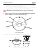
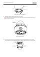
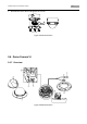
3. Fix the mounting base on the ceiling with screws.
Figure 3-53 Fix the Mounting Base
Note: If required, you can route cables through the side opening on the side of the mounting
base.
Figure 3-54 Side Opening
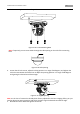
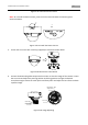
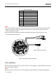
4. Loosen the tilt lock screws, adjust the tilting position in a range of 65 degrees, and tighten the
tilt lock screws. Rotate the black liner to adjust the panning position in a range of 360 degrees
until getting the desired surveillance angle.
Figure 3-55 Angle Adjusting
Note: As the lens of camera has already been factory adjusted to the best imaging effect, you just
need to adjust the panning position and tilting position to get the desired surveillance angle.
5. Reinstall the lower dome and tighten the screws.