
Installation manual

Installation Manual of Network Camera
25
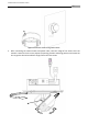
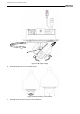
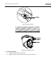
Figure 3-34 Route Cable through Side Outlet
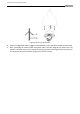
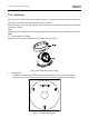
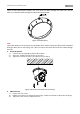
5. After connecting the network cable and power cable, view the image of the camera over the
network. Loosen the lock screws; adjust the panning position and tilting position and rotate the
lens to get the desired surveillance angle; fasten the lock screws.