
Installation manual

Installation Manual of Network Camera
15
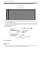
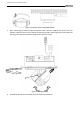
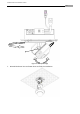
Figure 3-15 Overview
Table 3-2 Description
No.
Description
1
Video output interface
2
LINK: Indicator is solid yellow when network is connected.
3
ACT: Indicator flashes blue when network connection is functioning properly.
4
PWR: Indicator is solid red when the device is powered on.
5
Micro SD slot
6
RESET: Reset button
7
10M/100M self-adaptive Ethernet interface
8
Power supply interface
9
Extended interface
Notes:
The extended interface can be connected to alarm input/output interface, audio input/output
interface, RS-485 interface, etc.
To reset the default parameters to the camera, you need to press and hold the RESET button
and power on the camera. After the power on of the camera, you must still press and hold the
Reset button for about 20 seconds
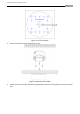
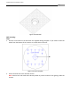
Camera wiring Diagram:
Figure 3-16 Wiring Diagram
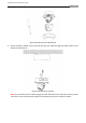
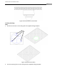
3.2.4 Installation
Ceiling mounting:
Steps:
1. Drill the screw holes on the ceiling with the supplied drilling template. If you need to route the
cables from the bottom of the camera, cut a cable hole in the ceiling.