Network Camera Installation Manual V5.0 Hangzhou Hikvision Digital Technology Co., Ltd. http://www.hikvision.com UD.
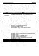
1 Installation Manual of Network Camera Thank you for purchasing our product. If there are any questions, or requests, please do not hesitate to contact the dealer. There is variety of structures of network cameras in our company. Installing instructions of all these cameras are listed in this manual. Find the model of your camera in the following list. Then according to the structure Type on the left of your camera Model, you can find corresponding chapter for instructions of your camera.
Installation Manual of Network Camera 2 This manual may contain several technical incorrect places or printing errors, and the content is subject to change without notice. The updates will be added to the new version of this manual. We will readily improve or update the products or procedures described in the manual. DISCLAIMER STATEMENT “Underwriters Laboratories Inc. (“UL”) has not tested the performance or reliability of the security or signaling aspects of this product.
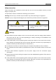
Installation Manual of Network Camera 3 Safety Instruction These instructions are intended to ensure that the user can use the product correctly to avoid danger or property loss. The precaution measure is divided into ‘Warnings’ and ‘Cautions’: Warnings: Serious injury or death may be caused if any of these warnings are neglected. Cautions: Injury or equipment damage may be caused if any of these cautions are neglected.
Installation Manual of Network Camera 4 Notice: Make sure the power supply voltage is correct before using the camera. Do not drop the camera or subject it to physical shock. Do not touch sensor modules with fingers. If cleaning is necessary, use a clean cloth with a bit of ethanol and wipe it gently. If the camera will not be used for an extended period of time, put on the lens cap to protect the sensor from dirt.
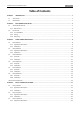
5 Installation Manual of Network Camera Table of Contents CHAPTER 1 INTRODUCTION .................................................................................................................................... 1 1.1 APPLICATIONS .......................................................................................................................................................... 1 1.2 PREPARATIONS...................................................................................................
Installation Manual of Network Camera 4.3.4 4.4 6 Installation ..................................................................................................................................................... 63 BULLET CAMERA IV ................................................................................................................................................. 65 4.4.5 Appearance ............................................................................................................
Installation Manual of Network Camera 1 Chapter 1 Introduction The network camera is a kind of embedded digital surveillance product that combines the features of both traditional analog camera and net DVS (Digital Video Server). With a built-in video server, the network camera is capable of providing real-time video stream compression, processing, video analysis and transmission simultaneously.
Installation Manual of Network Camera 2 Chapter 2 Box Camera Installation 2.1 Appearance Description 2.1.1 Box Camera I Camera description: Figure 2-1 Overview Table 2-1 Description No.
Installation Manual of Network Camera 3 Notes: To reset the default parameters to the camera, you need to press and hold the RESET button and power on the camera. After the power on of the camera, you must still press and hold the Reset button for about 20 seconds.
Installation Manual of Network Camera 4 Figure 2-3 Wiring Diagram 2.2 Installation Box camera I, II, III can be installed to wall or ceiling. Ceiling mounting is taken as an example in this section; if you adopt wall mounting, you can also take the below procedure as a reference. 2.2.2 Lens Installation Steps: 1. Remove the back cover from the lens mount. 2. Screw your lens (not provided) clockwise onto the lens mount of the camera.
Installation Manual of Network Camera 5 keyboards. Grounding The ground screw can be connected for grounding. 2.2.4 Mounting Before you start: These box cameras can be installed to wall or ceiling. Wall mounting is taken as an example in this section; if you adopt ceiling mounting, you can also take below procedure as a reference. Steps: 1. Attach the wall mount (not provided) to the wall and tighten the screws to fix it. Notes: The wall mount should be longer than 1/2 of the camera length.
Installation Manual of Network Camera 6 Figure 2-7 Mount the Camera Note: This camera is designed for indoor and outdoor use. To use the camera outdoors, it must be installed in an approved outdoor housing as shown in Figure 2-8. Figure 2-8 Wall Mounting with the Housing 4. Loosen the panning lock screw, you can adjust the panning angle of the camera up to 360° (Figure 2-9); Loosen the tilting lock screw, you can adjust the tilting angle of the camera up to 90° (Figure 2-10).
Installation Manual of Network Camera 7 Figure 2-10 Tilting
Installation Manual of Network Camera 8 Chapter 3 Dome Camera Installation 3.1 Dome Camera I 3.1.1 Appearance Description Camera description: Figure 3-1 Overview Table 3-1 Description No.
Installation Manual of Network Camera 9 Figure 3-2 Wiring Diagram 3.1.2 Installation Ceiling mounting: Note: If required, you can use a plier to remove the clip (one or two) on the side of the back box and then route cables through the opening to secure the cables on the ceiling. Figure 3-3 Remove the Clip Steps: 1. Use the screws to fix the mounting base to the ceiling; rotate the back box counterclockwise to secure it to the mounting base; use the lock screw to secure the dome camera.
Installation Manual of Network Camera 10 Figure 3-4 Mount the Camera 2. Loosen the set screws with the hex key (supplied) to remove the lower dome. Figure 3-5 Remove the Lower Dome 3. Connect the RCA analog video output with a monitor to view the image of the camera. Loosen the lens set screw and pan, tilt or rotate the lens to get a desired surveillance angle. Adjust the lens focus to obtain a perfect image. Fasten the lens set screw.
Installation Manual of Network Camera 11 4. Reinstall the lower dome and tighten the screws. Figure 3-7 Reinstall the Lower Dome In-ceiling mounting: Steps: 1. Secure the mounting base to the in-ceiling mounting base with screws. Figure 3-8 Secure the Mounting Base 2. Push the dome camera to the in-ceiling mounting base, rotate the dome camera for 10 degrees counterclockwise and then fasten the lock screws to fix the camera.
Installation Manual of Network Camera 12 Figure 3-9 Fix the Camera 3. Cut a 176~180 mm diameter hole in the ceiling and push the dome camera with in-ceiling mounting base to the hole. Note: The thickness of the ceiling should be less than 30 mm. Figure 3-10 Mount the Camera 4. It is strongly recommended that you use a safety rope to secure the in-ceiling mounting base to the roof.
Installation Manual of Network Camera 13 Figure 3-11 Safety rope 5. Fasten the lock screws to secure the dome camera. Figure 3-12 Secure the Camera 6. Remove the lower dome and connect the RCA analog video output with a monitor to view the image of the camera. Loosen the lens set screw and pan, tilt or rotate the lens to get a desired surveillance angle. Adjust the lens focus to obtain a perfect image. Fasten the lens set screw. Figure 3-13 Adjust the Image 7.
Installation Manual of Network Camera 14 Figure 3-14 Reinstall the Lower Dome 3.2 Dome Camera II 3.2.
Installation Manual of Network Camera 15 Figure 3-15 Overview Table 3-2 Description No. Description 1 Video output interface 2 LINK: Indicator is solid yellow when network is connected. 3 ACT: Indicator flashes blue when network connection is functioning properly. 4 PWR: Indicator is solid red when the device is powered on.
Installation Manual of Network Camera 16 Figure 3-17 Drill Template 2. Secure the back box to the ceiling with screws. Figure 3-18 Mount the Back Box 3. Loosen the set screws with the hex key (supplied) to remove the lower dome; remove the dome liner.
Installation Manual of Network Camera 17 Figure 3-19 Remove the Lower Dome 4. Install the dome module to the back box and pull the cables through the cable outlet on the bottom of the back box. Figure 3-20 Mount the Camera Note: If you need to pull the cable through the cable outlet from the side of the camera, please remove the cover and use water-proof joints and water-proof pipe to route the cables.
Installation Manual of Network Camera 18 Figure 3-21 Route Cable through Side Outlet 5. After connecting the network cable and power cable, view the image of the camera over the network. Loosen the lock screws; adjust the panning position and tilting position and rotate the lens to get the desired surveillance angle; fasten the lock screws. Figure 3-22 Adjust Image 6. Reinstall the dome liner and lower dome to finish the installation.
Installation Manual of Network Camera 19 Figure 3-23 Reinstall the Lower Dome In-ceiling mounting: Steps: 1. Drill the screw holes on the ceiling with the supplied drilling template. Figure 3-24 Drill Screw Holes 2. Cut the mounting holes on the ceiling with the supplied drilling template.
Installation Manual of Network Camera 20 Figure 3-25 Cut Mounting Hole 3. Loosen the set screws with the hex key (supplied) to remove the lower dome; remove the dome liner. Figure 3-26 Remove the Lower Dome 4.
Installation Manual of Network Camera 21 Figure 3-27 Mount the Camera 5. Fasten the toggle bolt and the toggle will automatically secure the dome module to the ceiling. Figure 3-28 Fasten the Bolts 6. After connecting the network cable and power cable, view the image of the camera over the network. Loosen the lock screws; adjust the panning position and tilting position and rotate the lens to get the desired surveillance angle; fasten the lock screws.
Installation Manual of Network Camera 22 Figure 3-29 Adjust Image 7. Reinstall the dome liner and lower dome to finish the installation.
Installation Manual of Network Camera 23 Figure 3-30 Reinstall Wall mounting: Steps: 1. Drill the screw holes on the wall with the supplied drilling template. If you need to route the cables from the bottom of the camera, cut a cable hole in the wall. Figure 3-31 Drill Template 2. Secure the back box to the wall with screws. Note: Position the side cable outlet directly below to prevent moisture from getting inside the camera.
Installation Manual of Network Camera 24 Figure 3-32 Secure the Back Box 3. Loosen the set screws with the hex key (supplied) to remove the lower dome; remove the dome liner. Figure 3-33 Remove the Lower Dome 4. Install the dome module to the back box and pull the cables through the cable outlet on the bottom of the back box. Note: If you need to pull the cable through the cable outlet from the side of the camera, please remove the cover and use water-proof joints and water-proof pipe to route the cables.
Installation Manual of Network Camera 25 Figure 3-34 Route Cable through Side Outlet 5. After connecting the network cable and power cable, view the image of the camera over the network. Loosen the lock screws; adjust the panning position and tilting position and rotate the lens to get the desired surveillance angle; fasten the lock screws.
Installation Manual of Network Camera 26 Figure 3-35 Adjust Image 6. Reinstall the dome liner and lower dome to finish the installation. Outdoor mounting: You can use DS-1242ZJ or DS-1243ZJ for outdoor mounting. DS-1242ZJ DS-1243ZJ Steps: 1. Remove the front panel and secure the bracket to the wall or ceiling. 2. Loosen the set screws with the hex key (supplied) to remove the lower dome; remove the dome liner. Figure 3-36 Remove the Lower Dome 3.
Installation Manual of Network Camera 27 Figure 3-37 Secure the Camera 4. Fasten the toggle bolt and the toggle will automatically secure the dome module to the bracket. 5. After connecting the network cable and power cable, view the image of the camera over the network. Loosen the lock screws; adjust the panning position and tilting position and rotate the lens to get the desired surveillance angle; fasten the lock screws.
Installation Manual of Network Camera 28 Figure 3-38 Adjust Image 6. Reinstall the dome liner and lower dome. Figure 3-39 Reinstall the Lower Dome 7. Reinstall the front panel to finish the installation.
Installation Manual of Network Camera 29 Figure 3-40 Reinstall the Front Panel 3.3 Dome Camera III 3.3.1 Overview Figure 3-41 Product Structure Diagram Table 1-1 Description NO.
Installation Manual of Network Camera 30 Note: Please make sure that the power adapter is compatible with the camera. This series of camera supports Power over Ethernet (PoE), and the standard power supply is 12V DC.
31 Installation Manual of Network Camera 3.3.2 Installation Before you start, please verify the package contents are correct by checking the items against the packing list, and make sure all the components are included. Wall mounting is preferred. We will take wall mounting as an example to explain the installation steps in this section. Note: Please make sure that the wall is strong enough to withstand three times the weight of the camera. Steps: 1.
32 Installation Manual of Network Camera There are two cable outlet methods. One is to route the cables through the cable hole, and the other is to route the cables through the side outlet shown below. Figure 3-44 Side Outlet Note: Three side outlets on the enclosure are selectable, which makes routing the cables easier instead of drilling a cable hole on the ceiling. Use a plier to remove the plastic and route the cables through the hole. 3. Install the Camera 1). 2). 3).
33 Installation Manual of Network Camera Figure 3-46 Lock Screw Figure 3-47 Adjust the Lens 5. Install the Trim Ring 1). 2). Attach the trim ring to the camera. Rotate the trim ring clockwise to secure it to the camera.
34 Installation Manual of Network Camera Figure 3-48 Install the Trim Ring Figure 3-49 Complete the Installation 3.
35 Installation Manual of Network Camera 3.4.3 Overview Figure 3-50 Overview Table 3-3 Physical Description No. 1 2 3 4 5 6 7 8 9 Description Mounting base Horizontal stand Vertical stand Lower dome Cables Plate of infrared lamp Lens Black Liner Safety rope 3.4.4 Installation Notes: Read the following contents carefully before the installation. Check the specification of the products for the installation environment.
36 Installation Manual of Network Camera Do not place the camera in extremely hot or damp environment. To avoid heat accumulation, good ventilation is required for a proper operating environment. If the product does not function properly, please contact your dealer or the nearest service center. Do not disassemble the camera for repair or maintenance by yourself. Ceiling mounting is recommended for this camera.
37 Installation Manual of Network Camera 3. Fix the mounting base on the ceiling with screws. Figure 3-53 Fix the Mounting Base Note: If required, you can route cables through the side opening on the side of the mounting base. Figure 3-54 Side Opening 4. Loosen the tilt lock screws, adjust the tilting position in a range of 65 degrees, and tighten the tilt lock screws. Rotate the black liner to adjust the panning position in a range of 360 degrees until getting the desired surveillance angle.
38 Installation Manual of Network Camera Figure 3-56 Reinstalling 3.5 Dome Camera V 3.5.5 Overview Figure 3-57 Overview No. 1 2 3 4 No.
39 Installation Manual of Network Camera 6 7 8 9 10 11 Infrared lamp Lower dome Status indicator RCA analog video output Debug Reset Note: After the power-on of the camera, pressing and holding the RESET button for about 10 seconds can reset all the parameters to the default settings. 3.5.6 Installation Notes: Read the following contents carefully before the installation. Check the specification of the products for the installation environment.
40 Installation Manual of Network Camera Figure 3-59 Fix the Ceiling Mount 3. Route the cables through the cable hole on the ceiling. Note: If required, you can rotate to remove the side cover on the mounting base and route the cables through the side outlet. Figure 3-60 Side Cover 4. Insert the three screws on the mounting base into the corresponding holes on the ceiling mount. Rotate the mounting base clockwise to secure the dome camera to the ceiling mount.
41 Installation Manual of Network Camera Figure 3-61 Install the Dome Camera Note: To uninstall the dome camera, press the lock screw and rotate the mounting base counterclockwise. A A 3:1 Figure 3-62 Uninstall the Dome Camera 5. Loosen the set screws with a hex key (supplied) to remove the lower dome. Figure 3-63 Remove the Lower Dome 6. Connect the RCA analog video output with a monitor to view the image of the camera.
42 Installation Manual of Network Camera 7. Reinstall the lower dome and tighten the screws. Figure 3-65 Reinstallation 3.6 Dome Camera VI 3.6.
43 Installation Manual of Network Camera No. 1 2 3 4 5 6 7 8 9 Table 1-3 Overview Description Lower Dome Black Liner Reset Button AUX Video Output Interface Serial Port Power interface Ethernet interface Mounting Base Lens Notes: To reset the default parameters to the camera, you need to press and hold the reset button and power on the camera. After the power on the camera, you must still press and hold the reset button for about 10 seconds.
44 Installation Manual of Network Camera Check the specification of the products for the installation environment. Make sure that all the related equipment is power-off during the installation. Check whether the power supply is matched with your AC outlet to avoid any damage. If the product does not function properly, please contact your dealer or the nearest service center. Do not disassemble the camera for repair or maintenance by yourself.
45 Installation Manual of Network Camera Cable Hole Drill Template Screw Hole Figure 3-69 The Drill Template 4. If you want to route the cables inside the ceiling, drill a cable hole in the ceiling according to the drill template. Skip this step, if you want to route the cables on the surface of the ceiling. Refer to Conduit Installation on the Side for side cable routing. 5. Attach the camera to the ceiling by aligning the holes of the back box with the holes on the ceiling. 6.
Installation Manual of Network Camera 46 11. Install the lower dome back to the camera and secure it with screws as shown in Figure 2-4. Figure 3-71 Secure Black Liner and Lower Dome Conduit Installation on the Side If you want to route the cables from side of the camera, you need to follow the steps below to install a conduit for cable routing. Steps: 1. Rotate the water-proof plug counterclockwise to remove it from the camera.
47 Installation Manual of Network Camera 2. Route the power cable and network cable through the side outlet to the conduit. 3. Align and rotate clockwise the conduit to the side outlet tightly. Conduit Figure 3-73 Install the Conduit to the Camera Note: For wall mounting, position the side outlet directly downward for water proofing.
48 Installation Manual of Network Camera 1. Disassemble the camera. Refer to the section 2.1. 2. Install the gang box in the ceiling. 3. Attach the mounting base to the gang box with two screws. Mounting Base Screw Hole Screw Hole Figure 3-75 In-ceiling Mount Figure 2-8 In-ceiling Mount 4. Route the cables through the hole in the center of the mounting base. 5. Align the camera with the mounting base. 6. Tighten the screws to secure the camera with the mounting base. 7.
49 Installation Manual of Network Camera Figure 3-76 Secure Camera 9. Install the inner black liner back to the camera. 10. Align the lower dome with the camera. 11. Tighten the screws to secure the lower dome with the camera as shown in Figure 2-7.
50 Installation Manual of Network Camera Figure 3-77 Secure Lower Dome 2.2.3 Wall Mounting For the wall mounting, you have to purchase a wall mount. Steps: 1. Disassemble the camera. 2. Install the wall mount and mounting adapter. 3. Align the screw holes of the mounting base with the corresponding screw holes of the mounting adapter. 4. Secure the mounting base to the mounting adapter with four screws.
51 Installation Manual of Network Camera Mounting Adaptor Figure 3-78 Install the Mounting Adapter
52 Installation Manual of Network Camera Mounting Base Figure 3-79 Secure Mounting Base 5. Route the cables through the hole in the center of the wall mount. 6. Align the camera with the mounting base. 7. Tighten the set screws to secure the camera with the mounting base. 8. Connect the video output connector to the monitor. Connect the power connector to the power supply. 9. Adjust the image and focus. Please refer to the section 2.3 for more detailed information.
53 Installation Manual of Network Camera Camera Figure 3-80 Secure Camera 10. Install the inner black liner back to the camera. 11. Align the lower dome with the camera. 12. Tighten the screws to secure the lower dome with the camera.
54 Installation Manual of Network Camera Black Liner Lower Dome Figure 3-81 Secure Black Liner and Lower Dome Image and Focus Adjusting Steps: 1. 1) 2) 3) 4) Three-axis adjustment. View the camera image using the monitor. Rotate the panning table to adjust the panning position of the camera. Rotate the tilting axes to adjust the tilting position of the camera. Rotate the lens table to adjust the azimuth angle of the image.
55 Installation Manual of Network Camera Panning Tilting Rotation Figure 3-82 Three-axis Adjustment 2. Zoom and focus adjustment. 1) View the camera image using the monitor. 2) Loosen the zoom lever and move the lever between T(Tele) and W(Wide) to obtain the appropriate angle of view. 3. Tighten the zoom lever. 1) Loosen the focus lever and move the lever between F(Far) and N(Near) to obtain the optimum focus. 2) Tighten the focus lever.
56 Installation Manual of Network Camera Lever Lever Figure 3-83 Lens Adjustment
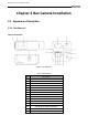
Installation Manual of Network Camera 57 Chapter 4 Bullet Camera Installation 4.1 Bullet Camera I 4.1.1 Appearance Description Camera description: Figure 4-1 Overview Figure 4-2 Overview Table 4-1 Description No.
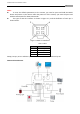
Installation Manual of Network Camera 58 Figure 4-3 Wiring Diagram 4.1.2 Installation Bullet camera can be installed to wall or ceiling. Wall mounting is taken as an example in this section; if you adopt ceiling mounting, you can also take below procedure as a reference. Steps: 1. Fix the mounting base to the wall. The mounting base can also be used to hide the cables.
Installation Manual of Network Camera 59 figure below). Fix the mounting bracket with the camera to the mounting base with screws. Note: The “bottom” mark on the mounting base should align with the “bottom” mark on the mounting bracket. Figure 4-5 Secure the Camera 3. View the image of the camera over the network. 4. Loosen the screws on the bracket slightly. Note: Please loosen the screws slightly until you can adjust the camera and do not remove the screws from the bracket. 5.
Installation Manual of Network Camera 60 Figure 4-8 Adjust the Lens 8. Fix the lens; reinstall the front cover and the sun shield to finish the installation. Note: Reinstall the front cover until aligning the mark on the front cover with the mark on the camera. Figure 4-9 Reinstall the Camera 4.2 Bullet Camera II 4.2.
Installation Manual of Network Camera 61 Figure 4-11 Overview Table 4-2 Description No. Description 1 10M/100M self-adaptive Ethernet interface 2 Power supply 3 Sun shade 4 Adjusting screw 4.2.2 Installation These bullet cameras can be installed to wall. Please refer to the steps below for installation. Steps: 1. Attach the wall mount(not provided) to the wall and tighten the screws to fix it. Notes: The wall mount should be longer than 1/2 of the camera length.
Installation Manual of Network Camera 62 Figure 4-13 Mount the Camera 4. Loosen the panning lock screw, you can adjust the panning angle of the camera up to 360° (Figure 2-9); Loosen the tilting lock screw, you can adjust the tilting angle of the camera up to 90° (Figure 2-10).
Installation Manual of Network Camera 63 4.3 Bullet Camera III 4.3.3 Appearance Description Figure 4-16 Bullet Camera Overview Sun Shield Back Box Grounding Screw Adjustable Bracket Reset Figure 4-17 Product Structure Diagram 4.3.4 Installation Note: Please make sure that the ceiling is strong enough to withstand three times the weight of the camera and the housing. Steps: 1.
Installation Manual of Network Camera The Ceiling 64 Expansion Screw Figure 4-18 Secure the Camera to the Ceiling 2. Three-Axis Adjustment Loosen the adjusting nuts on the bracket, and adjust the camera from P/R/T direction. P Direction: 0~360°adjustable. T Direction: 0~90°adjustable. R Direction: 0~360°adjustable Adjust the lens to the surveillance angle. Tighten the adjusting nuts to complete the installation.
Installation Manual of Network Camera 65 4.4 Bullet Camera IV 4.4.5 Appearance 2 1 3 Figure 4-20 Product Structure Diagram No. Name Description 1 Sun Shield Protection the camera 2 Lock Screw Secure the sun shield 3 Cables Power/Video Cable 4.4.6 Installation Before you start, please verify the package contents are correct by checking the items against the packing list, and make sure all the components are included. Wall mounting is preferred.
Installation Manual of Network Camera 66 2. Secure the Mount Secure the wall mount to the wall with the screws. Note: If the wall is the cement wall, you need to insert the expansion screws before you install the wall mount. If the wall is the wooden wall, you can use self-tapping screw to secure the wall mount. Figure 4-22 Secure the Wall Mount 3. Install the Camera Secure the camera to the wall mount with the screws.
67 Installation Manual of Network Camera 4.5 Bullet Camera V 4.5.1 Appearance 1 8 6 4 5 11 9 2 3 7 10 Figure 4-24 Overview No.
68 Installation Manual of Network Camera To reset the default parameters to the camera, you need to press and hold the reset button and power on the camera. After the power on the camera, you must still press and hold the reset button for about 10 seconds. The DS-2CD2612F-IS and DS-2CD2632F-IS models support audio and alarm functions. The Audio interfaces are shown as follows. Alarm Figure 4-25 Audio and Alarm Interfaces 4.5.
69 Installation Manual of Network Camera Figure 4-26 Disassemble the Camera 4. Insert the SD card to the SD card slot. 5. Rotate the front cover clockwise back to the camera and install the sun shield according to the arrow direction as shown in Figure 4-27(right). SD Card Slot Figure 4-27 Install the SD Card 6. Slide the sun shield according to the arrow direction as shown in Figure 4-28(left). 7. Rotate the TW M3X5 screw clockwise to tighten the sun shield.
70 Installation Manual of Network Camera Rotating Label Figure 4-28 Assemble the Camera Note: For water-proof, please align the rotating label on the front cover with that on the camera when you rotate the front cover clockwise. Refer to Figure 4-28(right). Mounting This camera is equipped with a bracket on the bottom. It can be mounted to a wall directly and can also be mounted to a wall with a junction box or a gang box. Wall mounting Steps: 1.
71 Installation Manual of Network Camera 2 Screw Hole 1 1 2 Cable Hole 2 2:Screw Hole for Mounting Base 1 1:Screw Hole for Bracket 1 2 Figure 4-29 Drilling Holes in the Wall 3. If you need to route cables through the wall (or ceiling), cut a cable hole according to the drill template. Skip this step, if you want to route the cables on the surface of the ceiling. 4. Route the cables of the camera. 5. Secure the camera to the wall (or ceiling) with expansion screws. Refer to the Figure 4-30.
72 Installation Manual of Network Camera Figure 4-30 Secure the Camera Wall Mounting with a Junction Box Before you start: For mounting with a junction box, you have to purchase a junction box. Steps: 1. Attach the drill template (supplied) to the wall where the camera is to be mounted. 2. Drill holes in the wall according to the number two holes of the drill template. Refer to the Figure 4-29. 3. If you need to route cables through the wall (or ceiling), cut a cable hole according to the drill template.
73 Installation Manual of Network Camera Junction Box Safety Rope Figure 4-31 Secure the Camera Wall Mounting with a Gang Box Before you start: For mounting with a gang box, you have to purchase a gang box. Steps: 1. Secure the camera attachment to a gang box with screws. 2. Route the cables of the camera. 3. Secure the camera to the camera attachment with screws.
74 Installation Manual of Network Camera View Angle Adjusting Purpose: 3-axis (pan/tilt/rotation) adjusting allows adjustment for optimum camera rotation and placement. You can use this function to get the angle of view that you want. Pan Adjustment Steps: 1. Loosen the lock screw-1. 2. Adjust the panning position of the camera. The adjusting range is from 0 degrees to 360 degrees. 3. Tighten the lock screw-1. Tilt Adjustment Steps: 1. Loosen the lock screw-2. 2. Adjust the tilting position of the camera.
75 Installation Manual of Network Camera 1. Disassemble the camera. Refer to section 2.1. 2. View the camera image using the monitor. 3. Loosen the zoom lever and move the lever between T(Tele) and W(Wide) to obtain the appropriate angle of view. 4. Tighten the zoom lever. 5. Loosen the focus lever and move the screw between F(Far) and N(Near) to obtain the optimum focus. 6. Tighten the focus lever. 7. Assemble the camera. Refer to section 2.1.
76 Installation Manual of Network Camera 5.1 Cube Camera I 5.1.1 Appearance Description Camera description: Figure 5-1 Overview Table 5-1 Description No. 1 2 3 4 5 6 7 8 9 10 11 Description Microphone Infrared light (Optional) Micro SD card slot LINK: Network status LED indicator. LED indicator is solid yellow when network connection is functioning properly. Power LED indicator, It is solid red when power is applied to the unit.
77 Installation Manual of Network Camera Figure 5-2 Wiring Diagram 5.1.2 Installation The cube camera can be installed to wall or ceiling. Ceiling mounting is taken as an example in this section; if you adopt wall mounting, you can also take below procedure as a reference. Steps: 1. Fix the bracket to the ceiling.
78 Installation Manual of Network Camera Figure 5-4 Mount the Camera 3. View the video image over the network. Loosen the knob on bracket to adjust the camera to the desired surveillance angle. Tighten the knob on bracket to secure the camera.
79 Installation Manual of Network Camera 5.2 Cube Camera II 5.2.3 Appearance Description Camera description: Figure 5-6 Overview Table 5-2 Description No. 1 2 3 4 5 6 7 8 9 10 11 12 13 14 Description Photosensitive resistance Infrared light PIR sensor Microphone Lens Alarm: Indicator is solid red when the camera is armed with PIR and access control and it is solid blue when the camera is unarmed. Indicator flashes blue when movement or presence is detected in its field of view.
80 Installation Manual of Network Camera 15 16 Power supply interface 10M / 100M self-adaptive Ethernet interface & PoE Note: To reset the default parameters to the camera, you need to press and hold the RESET button and power on the camera. After the power on of the camera, you must still press and hold the Reset button for about 20 seconds. Camera wiring diagram: Figure 5-7 Wiring Diagram 5.2.4 Installation The cube camera can be installed to wall, ceiling or table.
81 Installation Manual of Network Camera Note: If you want to install the battery, then you can take this step. Battery Battery Cover Figure 5-9 Insert Battery 3. Stick the drilling template to the ceiling. Notes: For cement ceiling mounting, you need to use expansion screw to fix the camera, and the hole of the expansion pipe should align with the mounting hole of the drilling template. For wooden ceiling mounting, you can just use the self-tapping screw to fix the camera.
82 Installation Manual of Network Camera Figure 5-11 Secure the Camera 5. Connect the network cable and power cable; reinstall the right cover and fixator. Note: If you need to pull the cable through the side cable outlet of the camera, pull the cables from the slot without reinstall the fixator. Slot Figure 5-12 Reinstall 6. Adjust Image. 1) View the image of the camera over the network. 2) Loosen the packing nut 1 to adjust the panning position and tilting position. 3) Fasten the packing nut 1.
83 Installation Manual of Network Camera Packing Nut 1 Pan Packing Nut 2 Tilt Figure 5-13 Adjust Image
84 Installation Manual of Network Camera Chapter 6 Mini Dome Camera Installation 6.1 Appearance Description Camera description: Figure 6-1 Overview Table 6-1 Description No. 1 2 3 4 5 6 7 Description Cover Lens P: Power LED indicator, It is solid red when power is applied to the unit. Base plate Set screw hole Set screw of lens S & L: Network status LED indicator. When the network is connected, the “S” LED is solid yellow, while the “L” LED flashes orange. RESET: Reset button.
85 Installation Manual of Network Camera Figure 6-2 Wiring Diagram 6.2 Installation The ceiling mounting is recommended for this camera. Note: If required, you can use a plier to remove the clip on the side of the back box and then route cables through the opening to secure the cables on the ceiling. Figure 6-3 Remove the Clip Steps: 1. Loosen the set screws with a hex key (supplied) to remove the cover.
86 Installation Manual of Network Camera 2. Use the screws to fix the base plate on the ceiling. Figure 6-5 Fix the Base Plate 3. View the video image of the camera over the network. 4. Loosen the lens set screws. Figure 6-6 Loosen Set Screws 5. Insert the hex key into the hole marked in the Figure 6-7 and rotate the hex key to adjust the panning position and tilting position until getting the desired surveillance angle. Tighten the set screws.
87 Installation Manual of Network Camera Figure 6-7 Adjust Image Notes: As the lens of camera has already been factory adjusted to the best imaging effect, you just need to adjust the panning position and tilting position to get the desired surveillance angle. Reinstall the cover before viewing the image of the camera because you may get an unclear image without the cover. 6. Reinstall the cover, and tighten the set screws.
88 Installation Manual of Network Camera Figure 6-8 Reinstall Figure 6-9 Reinstall