Network Fisheye Camera User Manual V5.0.9 UD.
User Manual of Network Fisheye Camera Thank you for purchasing our product. If there are any questions, or requests, please do not hesitate to contact the dealer. This manual applies to DS-2CD6362F-I (V) (S), DS-2CD6332FWD-I (V) (S) network fisheye camera. This manual may contain several technical incorrect places or printing errors, and the content is subject to change without notice. The updates will be added to the new version of this manual.
User Manual of Network Fisheye Camera Regulatory Information FCC Information FCC compliance: This equipment has been tested and found to comply with the limits for a digital device, pursuant to part 15 of the FCC Rules. These limits are designed to provide reasonable protection against harmful interference when the equipment is operated in a commercial environment.
User Manual of Network Fisheye Camera Safety Instruction These instructions are intended to ensure that the user can use the product correctly to avoid danger or property loss. The precaution measure is divided into ‘Warnings’ and ‘Cautions’: Warnings: Serious injury or death may be caused if any of these warnings are neglected. Cautions: Injury or equipment damage may be caused if any of these cautions are neglected.
User Manual of Network Fisheye Camera Cautions: Make sure the power supply voltage is correct before using the camera. Do not drop the camera or subject it to physical shock. Do not touch sensor modules with fingers. If cleaning is necessary, use a clean cloth with a bit of ethanol and wipe it gently. If the camera will not be used for an extended period of time, put on the lens cap to protect the sensor from dirt. Do not aim the camera lens at the strong light such as sun or incandescent lamp.
User Manual of Network Fisheye Camera Table of Contents Chapter 1 System Requirement .............................................................................. 7 Chapter 2 Network Connection ............................................................................. 8 2.1 Setting the Network Camera over the LAN......................................................... 8 2.1.1 Wiring over the LAN ....................................................................................................
User Manual of Network Fisheye Camera 5.4.2 Configuring Audio Settings ............................................................................................ 42 5.4.3 Configuring ROI Encoding ............................................................................................. 43 5.5 Configuring Image Parameters .......................................................................... 45 5.5.1 Configuring Display Settings ................................................................
User Manual of Network Fisheye Camera Chapter 1 System Requirement Operating System: Microsoft Windows XP SP1 and above version / Vista / Win7 / Server 2003 / Server 2008 32bits CPU: Intel Pentium IV 3.0 GHz or higher RAM: 1G or higher Display: 1024×768 resolution or higher Web Browser: Internet Explorer 6.0 and above version, Safari 5.02 and above version, Mozilla Firefox 3.5 and above version and Google Chrome8 and above versions.
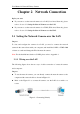
User Manual of Network Fisheye Camera Chapter 2 Network Connection Before you start: If you want to set the network camera via a LAN (Local Area Network), please refer to Section 2.1 Setting the Network Camera over the LAN. If you want to set the network camera via a WAN (Wide Area Network), please refer to Section 2.2 Setting the Network Camera over the WAN. 2.
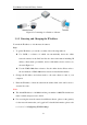
User Manual of Network Fisheye Camera Figure 2-2 Connecting via a Switch or a Router 2.1.2 Detecting and Changing the IP Address You need the IP address to visit the network camera. Steps: 1. To get the IP address, you can choose either of the following methods: Use SADP, a software tool which can automatically detect the online network cameras in the LAN and list the device information including IP address, subnet mask, port number, device serial number, device version, etc., shown in Figure 2-3.
User Manual of Network Fisheye Camera Figure 2-3 SADP Interface 2.2 Setting the Network Camera over the WAN Purpose: This section explains how to connect the network camera to the WAN with a static IP or a dynamic IP. 2.2.1 Static IP Connection Before you start: Please apply a static IP from an ISP (Internet Service Provider). With the static IP address, you can connect the network camera via a router or connect it to the WAN directly. Connecting the network camera via a router Steps: 1.
User Manual of Network Fisheye Camera 2. Assign a LAN IP address, the subnet mask and the gateway. Refer to Section 2.1.2 Detecting and Changing the IP Address for detailed IP address configuration of the camera. 3. Save the static IP in the router. 4. Set port mapping, e.g., 80, 8000, and 554 ports. The steps for port mapping vary according to the different routers. Please call the router manufacturer for assistance with port mapping. Note: Refer to Appendix 2 for detailed information about port mapping.
User Manual of Network Fisheye Camera 1. Connect the network camera to the router. 2. In the camera, assign a LAN IP address, the subnet mask and the gateway. Refer to Section 2.1.2 Detecting and Changing the IP Address for detailed LAN configuration. 3. In the router, set the PPPoE user name, password and confirm the password. 4. Set port mapping. E.g. 80, 8000, and 554 ports. The steps for port mapping vary depending on different routers.
User Manual of Network Fisheye Camera Figure 2-7 Normal Domain Name Resolution Steps: 1. Apply a domain name from a domain name provider. 2. Configure the DDNS settings in the DDNS Settings interface of the network camera. Refer to Section 5.3.4 Configuring DDNS Settings for detailed configuration. 3. Visit the camera via the applied domain name. Private Domain Name Resolution Figure 2-8 Private Domain Name Resolution Steps: 1. Install and run the IP Server software in a computer with a static IP. 2.
User Manual of Network Fisheye Camera Chapter 3 Access to the Network Camera 3.1 Accessing by Web Browsers Steps: 1. Open the web browser. 2. Input the IP address of the network camera in the address bar, e.g., 192.0.0.64 and press the Enter key to enter the login interface. 3. Input the user name and password and click Login. Figure 3-1 Login Interface Notes: The default user name is admin, and the default password is 12345.
User Manual of Network Fisheye Camera Figure 3-2 Download and Install Plug-in Figure 3-3 Install Plug-in (1) Figure 3-4 Install Plug-in (2) Note: You may have to close the web browser to install the plug-in. Please reopen the web browser and log in again after installing the plug-in.
User Manual of Network Fisheye Camera 3.2 Accessing by Client Software The product CD contains the iVMS-4200 client software. You can view the live video and manage the camera with the software. Follow the installation prompts to install the software. The control panel and live view interface of iVMS-4200 client software are shown as bellow. Figure 3-5 iVMS-4200 Client Software Note: For detailed information about the software, please refer to the user manual of the iVMS-4200 Client Software.
User Manual of Network Fisheye Camera Chapter 4 Live View 4.1 Live View Page Purpose: The live view page allows you to view the real-time video, capture images, realize PTZ control, set/call presets and configure video parameters. Log in the network camera to enter the live view page, or you can click Live View on the menu bar of the main page to enter the live view page.
User Manual of Network Fisheye Camera Operations on the live view page, e.g., live view, capture, record, audio on/off, two-way audio, etc. PTZ Control: Panning, tilting and zooming actions, and the PTZ speed of the camera. Preset/Patrol Settings: Set and call the preset/patrol for the camera. 4.2 Starting Live View In the live view window as shown in Figure 4-2, click on the toolbar to start the live view of the camera.
User Manual of Network Fisheye Camera 4.4 Operating PTZ Control Purpose: In the live view interface, you can use the PTZ control buttons to realize pan/tilt/zoom control of the camera. If the expand mode is 1 fisheye + 3 PTZ or 1 panorama + 3 PTZ, you can use the PTZ control interface to adjust the view angle and the PTZ speed. 4.4.1 PTZ Control Panel On the live view page, click to show the PTZ control panel or click to hide it. Click the direction buttons to control the pan/tilt movements.
User Manual of Network Fisheye Camera Figure 4-4 Setting a Preset 2. Use the PTZ control buttons to move the lens to the desired position. • Pan the camera to the right or left. • Tilt the camera up or down. • Zoom in or out. 3. Click to finish the setting of the current preset. 4. You can click to delete the preset. Note: You can configure up to 128 presets. Calling a Preset: This feature enables the camera to point to a specified preset scene manually when an event takes place.
User Manual of Network Fisheye Camera 4.4.3 Setting / Calling a Patrol Note: No less than 2 presets have to be configured before you set a patrol. Steps: 1. Click 2. 3. 4. 5. to enter the patrol configuration interface. Select a path No., and click to add the configured presets. Select the preset, and input the patrol duration and patrol speed. Click OK to save the first preset. Follow the steps above to add the other presets. Figure 4-6 Add Patrol Path 6. Click to save a patrol. 7.
User Manual of Network Fisheye Camera Chapter 5 Network Camera Configuration 5.1 Configuring Local Parameters Note: The local configuration refers to the parameters of the live view, record files and captured pictures. The record files and captured pictures are the ones you record and captured using the web browser and thus the saving paths of them are on the PC running the browser. Steps: 1.
User Manual of Network Fisheye Camera streaming under some network environments. MULTICAST: It’s recommended to select MCAST type when using the Multicast function. For detailed information about Multicast, refer to Section 5.3.1 TCP/IP Settings. Live View Performance: Set the live view performance to Shortest Delay, Real Time, Balanced or Best Fluency.
User Manual of Network Fisheye Camera 5.2 Configuring Time Settings Purpose: You can follow the instructions in this section to configure the time synchronization and DST settings. Steps: 1. Enter the Time Settings interface: Configuration > Basic Configuration > System > Time Settings Or Configuration > Advanced Configuration > System > Time Settings Figure 5-2 Time Settings Select the Time Zone. Select the Time Zone of your location from the drop-down menu. Synchronizing Time by NTP Server.
User Manual of Network Fisheye Camera Figure 5-3 Time Sync by NTP Server Note: If the camera is connected to a public network, you should use a NTP server that has a time synchronization function, such as the server at the National Time Center (IP Address: 210.72.145.44). If the camera is set in a customized network, NTP software can be used to establish a NTP server for time synchronization.
User Manual of Network Fisheye Camera 5.3 Configuring Network Settings 5.3.1 Configuring TCP/IP Settings Purpose: TCP/IP settings must be properly configured before you operate the camera over network. The camera supports both the IPv4 and IPv6. Both versions may be configured simultaneously without conflicting to each other, and at least one IP version should be configured. Steps: 1.
User Manual of Network Fisheye Camera Notes: The valid value range of MTU is 500 ~ 1500. The Multicast sends a stream to the multicast group address and allows multiple clients to acquire the stream at the same time by requesting a copy from the multicast group address. Before utilizing this function, you have to enable the Multicast function of your router. 3. Click Save to save the above settings. Note: A reboot is required for the settings to take effect. 5.3.
User Manual of Network Fisheye Camera No. which is not occupied. Server Port: The default server port number is 8000, and it can be changed to any port No. ranges from 2000 to 65535. 3. Click Save to save the settings. Note: A reboot is required for the settings to take effect. 5.3.3 Configuring PPPoE Settings Steps: 1. Enter the PPPoE Settings interface: Configuration >Advanced Configuration > Network > PPPoE Figure 5-8 PPPoE Settings 2. Check the Enable PPPoE checkbox to enable this feature. 3.
User Manual of Network Fisheye Camera the camera. Steps: 1. Enter the DDNS Settings interface: Configuration > Advanced Configuration > Network > DDNS Figure 5-9 DDNS Settings 2. Check the Enable DDNS checkbox to enable this feature. 3. Select DDNS Type. Four DDNS types are selectable: HiDDNS, IPServer , DynDNS and NO-IP. DynDNS: Steps: (1)Enter Server Address of DynDNS (e.g. members.dyndns.org). (2)In the Domain text field, enter the domain name obtained from the DynDNS website.
User Manual of Network Fisheye Camera Figure 5-10 DynDNS Settings IP Server: Steps: (1) Enter the Server Address of the IP Server. (2) Click Save to save the settings. Note: For the IP Server, you have to apply a static IP, subnet mask, and gateway and preferred DNS from the ISP. The Server Address should be entered with the static IP address of the computer that runs the IP Server software. Figure 5-11 IPServer Settings Note: For the US and Canada area, you can enter 173.200.91.
User Manual of Network Fisheye Camera Figure 5-12 NO-IP DNS Settings (2) Enter the Server Address as www.noip.com (3) Enter the Domain name you registered. (4) Enter the Port number, if needed. (5) Enter the User Name and Password. (6) Click Save and then you can view the camera with the domain name. HiDDNS Steps: (1) Choose the DDNS Type as HiDDNS. Figure 5-13 HiDDNS Settings (2) Enter the Server Address www.hik-online.com. (3) Enter the Domain name of the camera.
User Manual of Network Fisheye Camera 5.3.5 Configuring SNMP Settings Purpose: You can set the SNMP function to get camera status, parameters and alarm related information and manage the camera remotely when it is connected to the network. Before you start: Before setting the SNMP, please download the SNMP software and manage to receive the camera information via SNMP port. By setting the Trap Address, the camera can send the alarm event and exception messages to the surveillance center.
User Manual of Network Fisheye Camera Figure 5-14 SNMP Settings 2. Check the corresponding version checkbox ( , , ) to enable the feature. 3. Configure the SNMP settings. Note: The settings of the SNMP software should be the same as the settings you configure here. 4. Click Save to save and finish the settings. Note: A reboot is required for the settings to take effect. 5.3.6 Configuring 802.1X Settings Purpose: The IEEE 802.
User Manual of Network Fisheye Camera connecting the camera to the network protected by the IEEE 802.1X. Before you start: The authentication server must be configured. Please apply and register a user name and password for 802.1X in the server. Steps: 1. Enter the 802.1X Settings interface: Configuration > Advanced Configuration > Network > 802.1X Figure 5-15 802.1X Settings 2. Check the Enable IEEE 802.1X checkbox to enable the feature. 3. Configure the 802.
User Manual of Network Fisheye Camera Configuration >Advanced Configuration > Network > QoS Figure 5-16 QoS Settings 2. Configure the QoS settings, including video / audio DSCP, event / alarm DSCP and Management DSCP. The valid value range of the DSCP is 0-63. The bigger the DSCP value is, the higher the priority is. Note: DSCP refers to the Differentiated Service Code Point; and the DSCP value is used in the IP header to indicate the priority of the data. 3. Click Save to save the settings.
User Manual of Network Fisheye Camera Figure 5-17 Configure UPnP Settings 5.3.9 Email Sending Triggered by Alarm Purpose: The system can be configured to send an Email notification to all designated receivers if an alarm event is detected, e.g., motion detection event, video loss, video tampering, etc. Before you start: Please configure the DNS Server settings under Basic Configuration > Network > TCP/IP or Advanced Configuration > Network > TCP/IP before using the Email function. Steps: 1.
User Manual of Network Fisheye Camera Figure 5-18 Email Settings 3. Configure the following settings: Sender: The name of the email sender. Sender’s Address: The email address of the sender. SMTP Server: The SMTP Server IP address or host name (e.g., smtp.263xmail.com). SMTP Port: The SMTP port. The default TCP/IP port for SMTP is 25 (not secured). And the SSL SMTP port is 465. Enable SSL: Check the checkbox to enable SSL if it is required by the SMTP server.
User Manual of Network Fisheye Camera this checkbox to use authentication to log in to this server and enter the login user Name and password. Choose Receiver: Select the receiver to which the email is sent. Up to 2 receivers can be configured. Receiver: The name of the user to be notified. Receiver’s Address: The email address of user to be notified. 4. Click Save to save the settings. 5.3.10 Configuring NAT (Network Address Translation) Settings Purpose: 1. Enter the NAT settings interface.
User Manual of Network Fisheye Camera 5.3.11 Configuring FTP Settings Purpose: You can configure the FTP server related information to enable the uploading of the captured pictures to the FTP server. The captured pictures can be triggered by events or a timing snapshot task. Steps: 1. Enter the FTP Settings interface: Configuration >Advanced Configuration > Network > FTP Figure 5-20 FTP Settings 2. Configure the FTP settings; and the user name and password are required for login the FTP server.
User Manual of Network Fisheye Camera Figure 5-21 FTP Settings Note: The anonymous access function must be supported by the FTP server. 3. Click Save to save the settings. Note: If you want to upload the captured pictures to FTP server, you have to enable the continuous snapshot or event-triggered snapshot on Snapshot page. For detailed information, please refer to the Section 6.3. 5.4 Configuring Video and Audio Settings 5.4.1 Configuring Video Settings Steps: 1.
User Manual of Network Fisheye Camera Figure 5-22 Configure Video Settings 2. Select the Stream Type of the camera to main stream (normal), sub-stream or third stream. The main stream is usually for recording and live viewing with good bandwidth, and the sub-stream and third stream can be used for live viewing when the bandwidth is limited. 3.
User Manual of Network Fisheye Camera Set the frame rate to 1/16~25 fps. The frame rate is to describe the frequency at which the video stream is updated and it is measured by frames per second (fps). A higher frame rate is advantageous when there is movement in the video stream, as it maintains image quality throughout. Max. Bitrate: Set the max. bitrate to 32~16384 Kbps. The higher value corresponds to the higher video quality, but the higher bandwidth is required.
User Manual of Network Fisheye Camera Figure 5-23 Audio Settings 2. Configure the following settings. Audio Encoding: G.711 ulaw, G.711alaw, G.726, and MP2L2 are selectable. And 32kbps, 64kbps, and 128kbps are supported if MP2L2 is selected. Audio Input: MicIn and Linein are selectable for the connected microphone and pickup respectively. Input Volume: 0-100 Environmental Noise Filter: Set it as OFF or ON. When you set the function on the noise detected can be filtered. 3. Click Save to save the settings.
User Manual of Network Fisheye Camera Figure 5-24 Region of Interest Settings 2. Draw the region of interest on the image. There are four regions can be drawn. 3. Choose the stream type to set the ROI encoding. 4. Choose the ROI type. There are two options for ROI encoding, the fixed region encoding and the dynamic tracking. The fixed region encoding is the ROI encoding for the manually configured area.
User Manual of Network Fisheye Camera 5.5 Configuring Image Parameters 5.5.1 Configuring Display Settings Purpose: You can set the image quality of the camera, including brightness, contrast, saturation, hue, sharpness, etc. Note: The display parameters vary according to the different camera model. Please refer to the actual interface for details. Steps: 1.
User Manual of Network Fisheye Camera Brightness describes bright of the image, which ranges from 1~100, and the default value is 50. Contrast describes the contrast of the image, which ranges from 1~100, and the default value is 50. Hue adjusts color of the image. Saturation describes the colorfulness of the image color, which ranges from 1~100, and the default value is 50. Sharpness describes the edge contrast of the image, which ranges from 1~100, and the default value is 50.
User Manual of Network Fisheye Camera to the configured time period. Triggered by Alarm Input: The camera switches to the day mode or the night mode after the alarm is triggered. Backlight Settings BLC: If you focus on an object against strong backlight, the object will be too dark to be seen clearly. BLC compensates light to the object in the front to make it clear. OFF, Up, Down, Left, Right, Center and customize are selectable.
User Manual of Network Fisheye Camera 5.5.2 Configuring OSD Settings Purpose: You can customize the camera name and time on the screen. Steps: 1. Enter the OSD Settings interface: Configuration > Advanced Configuration > Image > OSD Settings Figure 5-28 OSD Settings 2. Check the corresponding checkbox to select the display of camera name, date or week if required. 3. Edit the camera name in the text field of Camera Name. 4.
User Manual of Network Fisheye Camera Figure 5-29 Adjust OSD Location 6. Click Save to activate above settings. 5.5.3 Configuring Privacy Mask Purpose: Privacy mask enables you to cover certain areas on the live video to prevent certain spots in the surveillance area from being live viewed and recorded. Steps: 1. Enter the Privacy Mask Settings interface: Configuration > Advanced Configuration> Image > Privacy Mask 2. Check the checkbox of Enable Privacy Mask to enable this function. 3. Click Draw Area.
User Manual of Network Fisheye Camera 4. Click and drag the mouse in the live video window to draw the mask area. Note: You are allowed to draw up to 4 areas on the same image. 5. Click Stop Drawing to finish drawing or click Clear All to clear all of the areas you set without saving them. 6. Click Save to save the settings. 5.
User Manual of Network Fisheye Camera Figure 5-31 Enable Motion Detection (3)Click . Click and drag the mouse on the live video image to draw a motion detection area. Note: You can draw up to 8 motion detection areas on the same image. (4)Click to finish drawing. Note: You can click to clear all of the areas. (5)(Optional) Move the slider to set the sensitivity of the detection. 2. Set the Arming Schedule for Motion Detection.
User Manual of Network Fisheye Camera (1)Click to edit the arming schedule. The Figure 5-28 shows the editing interface of the arming schedule. (2)Choose the day you want to set the arming schedule. (3)Click to set the time period for the arming schedule. (4)After you set the arming schedule, you can copy the schedule to other days (Optional). (5)Click to save the settings. Note: The time of each period can’t be overlapped. Up to 4 periods can be configured for each day.
User Manual of Network Fisheye Camera Figure 5-34 Linkage Method Steps: (1) Check the checkbox to select the linkage method. Notify surveillance center, send email, upload to FTP, trigger channel and trigger alarm output are selectable (Optional). Notify Surveillance Center Send an exception or alarm signal to remote management software when an event occurs. Send Email Send an email with alarm information to a user or users when an event occurs.
User Manual of Network Fisheye Camera Trigger one or more external alarm outputs when an event occurs. Note: To trigger an alarm output when an event occurs, please refer to Section 5.6.4 to set the related parameters. 5.6.2 Configuring Video Tampering Alarm Purpose: You can configure the camera to trigger the alarm when the lens is covered and take alarm response action. Steps: 1.
User Manual of Network Fisheye Camera 5.6.1. 5. Check the checkbox to select the linkage method taken for the tamper-proof. Audible warning, notify surveillance center, send email and trigger alarm output are selectable. Please refer to Task 3 Set the Alarm Actions for Motion Detection in Section 5.6.1. 6. Click to save the settings. 5.6.3 Configuring Alarm Input Steps: 1. Enter the Alarm Input Settings interface: Configuration > Advanced Configuration> Events > Alarm Input: 2. Choose the alarm input No.
User Manual of Network Fisheye Camera installed with a pan/tilt unit. Check the relative checkbox and select the No. to enable Preset Calling, Patrol Calling or Pattern Calling. 6. You can copy your settings to other alarm inputs. 7. Click Save to save the settings. 5.6.4 Configuring Alarm Output Steps: 1. Enter the Alarm Output Settings interface: Configuration>Advanced Configuration> Events > Alarm Output 2. Select one alarm output channel in the Alarm Output drop-down list.
User Manual of Network Fisheye Camera Figure 5-37 Alarm Output Settings 5.6.5 Handling Exception The exception type can be HDD full, HDD error, network disconnected, IP address conflicted and illegal login to the cameras. Steps: 1. Enter the Exception Settings interface: Configuration > Advanced Configuration> Events > Exception 2. Check the checkbox to set the actions taken for the Exception alarm. Refer to Task 3: Set the Alarm Actions Taken for Motion Detection in Section 5.6.1.
User Manual of Network Fisheye Camera Chapter 6 Storage Settings Before you start: To configure record settings, please make sure that you have the network storage device within the network or the SD card inserted in your camera. 6.1 Configuring NAS Settings Before you start: The network disk should be available within the network and properly configured to store the recorded files, log files, etc. Steps: 1.
User Manual of Network Fisheye Camera Storage Management), in which you can view the capacity, free space, status, type and property of the disk. Figure 6-2 Storage Management Interface (2) If the status of the disk is Uninitialized, check the corresponding checkbox to select the disk and click Format to start initializing the disk. When the initialization completed, the status of disk will become Normal. Figure 6-3 View Disk Status 2. Define the quota for record and pictures.
User Manual of Network Fisheye Camera To initialize and use the SD card after insert it to the camera, please refer to the steps of NAS disk initialization. 6.2 Configuring Recording Schedule Purpose: There are two kinds of recording for the cameras: manual recording and scheduled recording. For the manual recording, refer to Section 4.3 Recording and Capturing Pictures Manually. In this section, you can follow the instructions to configure the scheduled recording.
User Manual of Network Fisheye Camera Figure 6-6 Record Parameters Pre-record: The time you set to start recording before the scheduled time or the event. For example, if an alarm triggers recording at 10:00, and the pre-record time is set as 5 seconds, the camera starts to record at 9:59:55. The Pre-record time can be configured as No Pre-record, 5 s, 10 s, 15 s, 20 s, 25 s, 30 s or not limited. Post-record: The time you set to stop recording after the scheduled time or the event.
User Manual of Network Fisheye Camera (1) Set all-day record or segment record: If you want to configure the all-day recording, please check the All Day checkbox. If you want to record in different time sections, check the Customize checkbox. Set the Start Time and End Time. Note: The time of each segment can’t be overlapped. Up to 4 segments can be configured. (2) Select a Record Type. The record type can be Continuous, Motion Detection, Alarm, Motion | Alarm, Motion & Alarm, etc.
User Manual of Network Fisheye Camera and alarm are triggered at the same time. Besides configuring the recording schedule, you have to configure the settings on the Motion Detection and Alarm Input Settings interfaces. Please refer to Section 5.6.1 and Section 5.6.3 for detailed information. Record Triggered by Motion | Alarm If you select Motion | Alarm, the video will be recorded when the external alarm is triggered or the motion is detected.
User Manual of Network Fisheye Camera 6.3 Configuring Snapshot Settings Purpose: You can configure the scheduled snapshot and event-triggered snapshot. The captured picture can be stored in the SD card (if supported) or the netHDD (For detailed information about netHDD, please refer to Section 6.1 Configuring NAS Settings). You can also upload the captured pictures to a FTP server. Basic Settings Steps: 1. Enter the Snapshot Settings interface: Configuration > Advanced Configuration > Storage > Snapshot 2.
User Manual of Network Fisheye Camera 2) Check Upload Picture checkbox in Motion Detection Settings or Alarm Input interface. Please refer to Task 3: Set the Alarm Actions Taken for Motion Detection in Section 5.6.1. 3) Check the Enable Event-triggered Snapshot checkbox.
User Manual of Network Fisheye Camera Chapter 7 Playback Purpose: This section explains how to view the remotely recorded video files stored in the network disks or SD cards. Steps: 1. Click Playback on the menu bar to enter playback interface. Figure 7-1 Playback Interface 2. Select the date and click Search. Figure 7-2 Search Video 3. Click to play the video files found on this date.
User Manual of Network Fisheye Camera The toolbar on the bottom of Playback interface can be used to control playing process.
User Manual of Network Fisheye Camera Chapter 8 Log Searching Purpose: The operation, alarm, exception and information of the camera can be stored in log files. You can also export the log files on your demand. Before you start: Please configure network storage for the camera or insert a SD card in the camera. Steps: 1. Click Log on the menu bar to enter log searching interface. Figure 8-1 Log Searching Interface 2.
User Manual of Network Fisheye Camera Chapter 9 Others 9.1 Managing User Accounts Enter the User Management interface: Configuration >Basic Configuration> Security > User Or Configuration > Advanced Configuration> Security > User The admin user has access to create, modify or delete other accounts. Up to 15 user accounts can be created. Figure 9-1 User Information Add a User Steps: 1. Click Add to add a user. 2. Input the new User Name, select Level and input Password.
User Manual of Network Fisheye Camera Figure 9-2 Add a User Modify a User Steps: 1. Left-click to select the user from the list and click Modify. 2. Modify the User Name, Level or Password. 3. In the Basic Permission field and Camera Configuration field, you can check or uncheck the permissions. 4. Click OK to finish the user modification.
User Manual of Network Fisheye Camera Delete a User Steps: 1. Click to select the user you want to delete and click Delete. 2. Click OK on the pop-up dialogue box to delete the user. 9.2 Configuring RTSP Authentication Purpose: You can specifically secure the stream data of live view. Steps: 1. Enter the RTSP Authentication interface: Configuration> Advanced Configuration> Security > RTSP Authentication Figure 9-4 RTSP Authentication 2.
User Manual of Network Fisheye Camera Figure 9-5 Anonymous Visit 2. Set the Anonymous Visit permission Enable or Disable in the drop-down list to enable or disable the anonymous visit. 3. Click Save to save the settings. There will be a checkbox of Anonymous by the next time you logging in. Figure 9-6 Login Interface with an Anonymous Checkbox 4. Check the checkbox of Anonymous and click Login. Note: Only live view is available for the anonymous user. 9.
User Manual of Network Fisheye Camera Figure 9-7 IP Address Filter Interface 2. Check the checkbox of Enable IP Address Filter. 3. Select the type of IP Address Filter in the drop-down list, Forbidden and Allowed are selectable. 4. Set the IP Address Filter list. Add an IP Address Steps: (1) Click the Add to add an IP. (2) Input the IP Adreess. Figure 9-8 Add an IP (3) Click the OK to finish adding. Modify an IP Address Steps: (1) Left-click an IP address from filter list and click Modify.
User Manual of Network Fisheye Camera (2) Modify the IP address in the text filed. Figure 9-9 Modify an IP (3) Click the OK to finish modifying. Delete an IP Address Left-click an IP address from filter list and click Delete. Delete all IP Addresses Click Clear to delete all the IP addrsses. 5. Click Save to save the settings. 9.
User Manual of Network Fisheye Camera Figure 9-10 Device Information 9.6 Maintenance 9.6.1 Rebooting the Camera Steps: 1. Enter the Maintenance interface: Configuration > Basic Configuration> System > Maintenance Or Configuration > Advanced Configuration> System > Maintenance: 2. Click Reboot to reboot the network camera. Figure 9-11 Reboot the Device 9.6.2 Restoring Default Settings Steps: 1.
User Manual of Network Fisheye Camera Figure 9-12 Restore Default Settings Note: After restoring the default settings, the IP address is also restored to the default IP address, please be careful for this action. 9.6.3 Exporting / Importing Configuration File Purpose: Configuration file is used for the batch configuration of the camera, which can simplify the configuration steps when there are a lot of cameras needing configuring.
User Manual of Network Fisheye Camera 9.6.4 Upgrading the System Steps: 1. Enter the Maintenance interface: Configuration > Basic Configuration> System > Maintenance Or Configuration > Advanced Configuration> System > Maintenance 2. Click Browse to select the local upgrade file and then click Upgrade to start remote upgrade. Note: The upgrading process will take 1 to 10 minutes. Please don't disconnect power of the camera during the process. The camera reboots automatically after upgrading.
User Manual of Network Fisheye Camera Figure 9-15 RS-232 Settings Note: If you want to connect the camera by the RS-232 port, the parameters of the RS-232 should be exactly the same with the parameters you configured here. 2. Click Save to save the settings. 9.8 RS-485 Settings Purpose: The RS-485 serial port is used to control the PTZ of the camera. The configuring of the PTZ parameters should be done before you control the PTZ unit. Steps: 1.
User Manual of Network Fisheye Camera 9.9 Fisheye Parameters Fisheye parameters configuration enables you to select the real-time mode, and the mounting type, etc. Figure 9-17 Fisheye Parameters Enable or disable the real-time mode by clicking the checkbox in front of the each option. Ceiling mounting, table mounting, and wall mounting are selectable for the mounting type. Select the proper mounting type according to your actual environment and demand.
User Manual of Network Fisheye Camera Appendix Appendix 1 SADP Software Introduction Description of SADP V 2.0 SADP (Search Active Devices Protocol) is a kind of user-friendly and installation-free online device search tool. It searches the active online devices within your subnet and displays the information of the devices. You can also modify the basic network information of the devices using this software.
User Manual of Network Fisheye Camera Search online devices manually You can also click Refresh to refresh the online device list manually. The newly searched devices will be added to the list. Note: You can click or information; you can click on each column heading to order the to expand the device table and hide the network parameter panel on the right side, or click to show the network parameter panel. Modify network parameters Steps: 1.
User Manual of Network Fisheye Camera 1. Contact our technical engineers to get the serial code. 2. Input the code in the Serial code field and click Confirm to restore the default password.
User Manual of Network Fisheye Camera Appendix 2 Port Mapping The following settings are for TP-LINK router (TL-WR641G). The settings vary depending on different models of routers. Steps: 1. Select the WAN Connection Type, as shown below: Figure A.2.1 Select the WAN Connection Type 2. Set the LAN parameters of the router as in the following figure, including IP address and subnet mask settings. Figure A.2.2 Set the LAN parameters 3. Set the port mapping in the virtual severs of Forwarding.
User Manual of Network Fisheye Camera another camera as 81, 8001, 555, 8201 with IP 192.168.1.24. Refer to the steps as below: Steps: 1. As the settings mentioned above, map the port 80, 8000, 554 and 8200 for the network camera at 192.168.1.23 2. Map the port 81, 8001, 555 and 8201 for the network camera at 192.168.1.24. 3. Enable ALL or TCP protocols. 4. Check the Enable checkbox and click Save. Figure A.2.3 Port Mapping Note: The port of the network camera cannot conflict with other ports.
User Manual of Network Fisheye Camera 85