Instruction manual
Manuals
Brands
Hikvision Digital Technology Manuals
Security Cameras
DS-2CD4032FWD-A
1
2
3
4
5
6
7
8
9
10
Table Of Contents
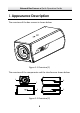
1 Appearance Description
2 Installation
2.1 Ceiling Mounting
2.2 Wall Mounting
2.3 Installing the SD Card
3 Setting the Network Camera over the LAN
4 Accessing via Web Browser
Network Box Camera
·
Quick Operation Guide
9
9
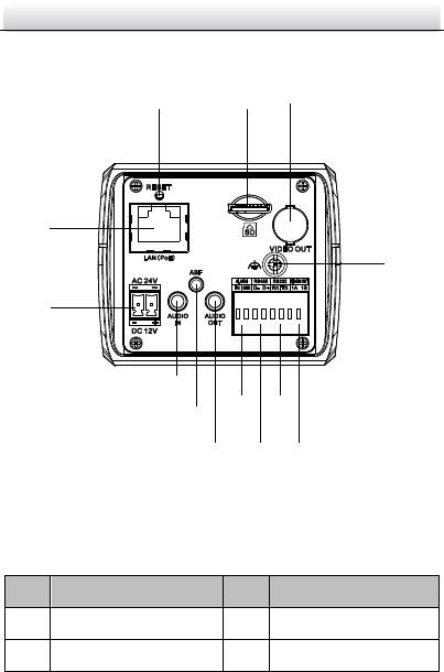
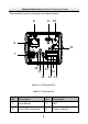
The interfaces on the rear panel are shown below:
Overview (3)
Figure 1-3
Description
Table 1-1
No.
Description
No.
Description
1
Lens Mount
2
MIC
3
¼
-20 UNC Screw Hole
4
Pow
er I
ndicat
or
8
6
9
10
7
18
16
11
17
14
13
15
12
1
...
...
8
9
10
11
12
...
...
30