Installation Guide INSTALL_GATEWAY-LITE-V7 2019/04 Edition Related HIKOB products: GATEWAY H-GL200A-T GATEWAY H-GL200A-P NETPULSEAPP H-SC18-T NETPULSEAPP H-SC18-P EXTENDER H-AT200A SMA AH-AC100A-50 ANT SH-AC100A This document may not be reproduced (even partially) or communicated to 3rd parties without the written authorization of the company’s General Management. Copyright © HIKOB.
Installation guide INSTALL_GATEWAY-LITE-V7 2019/04 Edition Table of contents 1. Introduction .................................................................................................... 3 1.1 Symbols and conventions used in this guide........................................................... 3 1.2 Safety instructions ................................................................................................... 3 1.1 Compliance and conformity ............................................
Installation guide INSTALL_GATEWAY-LITE-V7 2019/04 Edition 1. Introduction When using GATEWAY-LITE, safety precautions must be taken to avoid injury and damages. Please read this guide before installing, using the product, or performing any maintenance operation. Failure to read, understand and follow herein instructions may result in personal injury. In no event shall HIKOB be held liable for any damages arising out of or related to misunderstanding instructions detailed in this manual. 1.
Installation guide INSTALL_GATEWAY-LITE-V7 2019/04 Edition 1.1 Compliance and conformity a. Europe HIKOB SAS declares that the HIKOB GATEWAY LITE product is in accordance with stipulations of the RED 2014/53/UE, CEM 2014/30/UE and 2014/35/UE directives. b. USA Information to user: This device complies with part 15 of the FCC Rules.
Installation guide INSTALL_GATEWAY-LITE-V7 2019/04 Edition 1.3 WEEE Information on disposal for users of waste electrical electronical equipment: This symbol on the product(s) and / or accompanying documents means that used electrical and electronic products should not be mixed with general household waste. For proper treatment, recovery and recycling, please take this product(s) to designated collection points where it will be accepted free of charge.
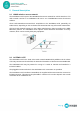
Installation guide INSTALL_GATEWAY-LITE-V7 2019/04 Edition 2 General description 2.1 HIKOB wireless sensor network The GATEWAY-LITE is part of the HIKOB wireless sensor network for vehicle detection. This radio network consists of a GATEWAY-LITE and a set of WISECOW sensors that detect vehicles. These radio-transmitters transmit their acquisitions to the GATEWAY-LITE, potentially via LION routers, depending on the environmental constraints that may affect radio transmission.
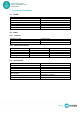
Installation guide INSTALL_GATEWAY-LITE-V7 2019/04 Edition 3 Technical information 3.1 Global Power supply Power consumption Dimensions Type of fixing Weight Operating temperature Water index 3.2 3.2.1 Between +6VDC and +24VDC < 100mW 77 x 60 x 25mm DIN Rail 150g From -40°C to 80°C IP20 Radio Common Frequency band Protocol Number of channels 3.2.2 Authorized antennas Manufacturer Manufacturer Part Number HIKOB Part Number Antenna gain 3.3 2.45GHz ISM IEEE 802.15.4e 16 Antenna 1 LPRS ANT-SS2.
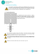
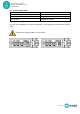
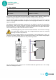
Installation guide INSTALL_GATEWAY-LITE-V7 2019/04 Edition 4 Guidelines for Installing The electrical connection for powering the GATEWAY-LITE as well as the connection to external equipment for reading the dry contact outputs must only be carried out by qualified and competent personnel. The installation must comply with the local electrical safety rules applicable for the installation site. 4.1 Mounting Dimensions The GATEWAY-LITE must be placed in a cabinet, mounted on a DIN rail.
Installation guide INSTALL_GATEWAY-LITE-V7 2019/04 Edition 4.2 Connecting Power Power supply Power consumption Connectors Wire sections Between +6VDC and +24VDC < 100mW Terminal block From AWG28 to AWG16 (0.08mm² à 1.3mm²) To power the GATEWAY-LITE (Class III appliance), a low-voltage DC power source must be used.
Installation guide INSTALL_GATEWAY-LITE-V7 2019/04 Edition 4.3 Dry contacts Number of dry contacts Breaking capability Connectors Wire sections 4 60V / 100mA Terminal block From AWG28 to AWG16 (0.08mm² to 1.3mm²) Dry contacts consist of isolated relays with breaking capability of 60V / 100mA. It’s easy to use standard voltages available in the technical cabinets, namely 12VDC and 24VDC. Use the shortest cable as possible and make sure it’s properly sized to carry the required current.
Installation guide INSTALL_GATEWAY-LITE-V7 2019/04 Edition 4.4 Configuration Serial Interface Type of interface Baud rate Data bits Parity Stop bit Flow control RS232 115200bauds 8 No 1 No The RS 232 port is used for the configuration of the GATEWAY-LITE, it can also be used in operation (notification, settings, etc.), refer to the documentation of the serial communication interface provided or contact the HIKOB support.
Installation guide INSTALL_GATEWAY-LITE-V7 2019/04 Edition 4.5 Exploitation Serial Interface Type of interface Baud rate Parity Stop bit Flow control RS485 2wire 9600bauds No 1 No The RS485 port is used to connect one or more EXTENDERs (slaves) to a GATEWAY-LITE (master) and thus expand the number of dry contacts available on the GATEWAY-LITE. If more than one EXTENDER is used with the same GATEWAY-LITE, it is necessary to modify the identifier of the additional EXTENDERs.
Installation guide INSTALL_GATEWAY-LITE-V7 2019/04 Edition 5 Exploitation Description of the different states of the LEDs: Indicators Description Alimentation The “power” LED is off: The equipment is not properly powered, refer to paragraph 4.2 The “power” LED is on: The equipment is properly powered For the LED’s definition associated with the outputs, refer to the GATEWAY-LITE -P -T or -W commissioning documentation for your application.