
User Manual


HF-Z100 ZigBee Module User Manual
Shanghai High-Flying Electronics Technology Co., Ltd(www.hi-flying.com) -7-
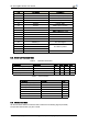
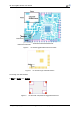
Figure 3. HF-Z100 Mechanical Dimension
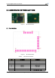
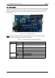
2.4. Antenna
HF-Z100 module support internal on-board chip antenna and external wire antenna
option.Wire antenna is flexible to avoid the metal affect or the other on RF performance in
LED lighting because it isnot fixed on board like chip antenna and can be go out externally.
The position for the assembly of wireantenna on board referto Figure 4, user can select
horizontal direction through the SMT PAD or vertical direction through the Through Hole PAD
based on dedicated application.
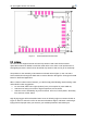
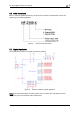
When customer select internal antenna, you shall comply with following antenna design rules
and module location suggestions:
For user PCB, RED color region (6x5mm) can’t put componet or paste GND net;
Antenna must away from metal or high components at least 10mm;
Antenna can’t be shieldedby any meal enclosure. All cover, include plastic, shall away
from antenna at least 10mm;
High-Flying suggest HF-Z100 module better locate in following region at customer board as
Figure 5, which to reduce the effect to antenna and wireless signal, and better consult High-
Flying technical people when you structure your module placement and PCB layout.