
User Manual


High-Flying
Low Power WiFi Module User Manual
Shanghai High-Flying Electronics Technology Co., Ltd
www.hi-flying.com
- 13 -
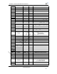
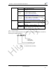
47 Module Reset EXT_RESETn I,PU “Low” effective reset input.
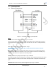
<Notes>
nReload Pin (Button) function:
1. When this pin is set to “low” during module boot up, the module will enter wireless
firmware and config upgrade mode. This mode is used for customer manufacture.
(High-Flying will provide software tools for customer batch configuration and
upgrade firmware during mass production)
2. After module is powered up, short press this button ( “Low” < 3s ) to make the
module go into “Smart Link “ config mode, waiting for APP to set password and
other information.
3. After module is powered up, long press this button ( “Low” > 3s ) to make the
module recover to factory setting.
High-Flying strongly suggest customer fan out this pin to connector or button for
“Manufacture” and “ Smart Link” application.
nLink Pin (LED) function:
1. At wireless firmware and config upgrade mode , this LED used to indicate configure
and upgrade status.
2. At “Smart Link “ config mode, this LED used to indicate APP to finish setting.
3. At normal mode, it’s Wi-Fi link status indicator
High-Flying strongly suggest customer fan out this pin to LED.
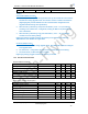
1.2.2. Electrical Characteristics
Absolute Maximum Ratings:
Parameter Condition Min. Typ. Max. Unit
Storage temperature range -45 125 °C
Maximum soldering temperature IPC/JEDEC J-STD-020 260 °C
Supply voltage 0 3.8 V
Voltage on any I/O pin 0 3.3 V
ESD (Human Body Model HBM) TAMB=25°C 2 KV
ESD (Charged Device Model, CDM) TAMB=25°C 1 KV
Power Supply & Power Consumption:
Parameter Condition Min. Typ. Max. Unit
Operating Supply voltage 2.8 3.3 3.8 V
Supply current, peak Continuous Tx 200 mA
Supply current, IEEE PS DTIM=100ms 12 mA
Output high voltage Sourcing 6mA 2.8 V
Output low voltage Sinking 6mA 0.2 V
Input high voltage 2.2 V
Input low voltage 0.8 V
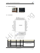
HF-SH01