
User's Manual


1.2.1. HF-LPT271Pins Definition
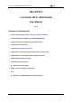
Figure 3. H
F-LPT271 Pins Map
Table2. HF-LPT271 Pins Definition
Pin
Describtion
Net Name
Signal
Type
Comments
1 Module Reset RESET I,PU
“Low” effective reset input. There is RC reset
circuit internally. Noneedof external RC reset
circuit.
2
GPIO11
I/O
GPIO11
3
GPIO17
I/O
BootSelect, default low,leaveitunconnected.
Low: boot from flash.
High: boot from UART.
4 GPIO20 GPIO20 I/O GPIO20
5 Multi-Function nReload I,PU
Detailed functions see <Notes>
GPIO3, PWM3
6
GPIO12
GPIO12
I/O
GPIO12
7
Module Boot Up
Indicator
nReady
O
“0” – Boot-up OK;
“1” – Boot-up Fail;
GPIO4, PWM2
8 +3.3V Power VDD Power
9
Ground
GND
Power
10
GPIO14
GPIO14
I/O
GPIO14
11
GPIO21
GPIO21
I/O
GPIO21
12
Wi-Fi Status
nLink
O
“0” – Wi-Fi connect to router
“1” – Wi-Fi unconncted;
Detailed functions see <Notes>
GPIO22
Shanghai High-Flying Electronics Technology Co., Ltd(www.hi-flying.com) - 9 -