
User's Manual


HF-LPX70 SeriesWi-Fi&BLE User Manual
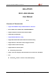
1.2.1. HF-LPT270 Pins Definition
Figure 3. HF-LPT270 Pins Map
Table2. HF-LPT270 Pins Definition
Pin
Describtion
Net Name
Signal
Type
Comments
1
UART1_TX
DEBUG_UART1_TX
O
3.3V TTL UART1 Debug Output
GPIO17
2 UART1_RX
DEBUG_UART1_RX
I
3.3V
TTL UART1 Debug Input
GPIO11
3
GPIO12
GPIO12
I/O
GPIO12
4
GPIO14
GPIO14
I/O
GPIO14
5
UART0
UART0_TX
O,PU
3.3V TTL UART0 Communication Output
GPIO16
6 UART0 UART0_RX I
3.3V
TTL UART0 Communication Input
GPIO7
7
GPIO8
I/O
BootSelect, default low,leaveitunconnected.
L
ow: boot from flash.
High: boot from UART.
8
NC
9 NC
10
Module Reset RESET I,PU
“Low” effective reset input. There is RC
reset circuit internal
ly. Noneedof external
RC reset circuit.
11
Module Boot
Up Indicator
nReady
O
“0” – Boot-up OK;
“1”
– Boot-up Fail;
GPIO4, PWM2
12
Multi-Function nReload I,PU
Detailed functions see <Notes>
GPIO3, PWM3
Shanghai High-Flying Electronics Technology Co., Ltd(www.hi-flying.com) - 8 -