
User Manual

High-Flying
HF-LPT200 Low Power WiFi Module User Manual
Shanghai High-Flying Electronics Technology Co., Ltd(www.hi-flying.com) - 11 -
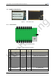
1.2. Hardware Introduction
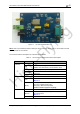
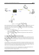
Figure 1. HF-LPT200 View
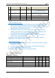
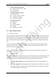
1.2.1. Pins Definition
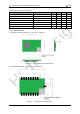
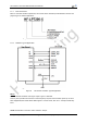
Figure 2. HF-LPT200 Pins Map
Table 2 HF-LPT200 Pins Definition
Pin
Describtion
Net Name
Signal
Type
Comments
1
SPI Data Out
SPI_MOSI
O
GPIO1, No connect if not use.
2
SPI Interface
SPI_CLK
I/O
GPIO2, No connect if not use.
3
SPI Data In
SPI_MISO
I
GPIO3, No connect if not use
4
SPI Interface
SPI_CS
I/O
GPIO4, No connect if not use
5
UART0
UART0_TX
O
GPIO5, No connect if not use
6
UART0
UART0_RX
I
GPIO6, No connect if not use.
7
UART0
UART0_CTS
I/O
GPIO7, No connect if not use.
8
UART0
UART0_RTS
I/O
GPIO8, No connect if not use.
9
GPIO9
GPIO9
I,PU
GPIO9, No connect if not use.
10
Module Reset
EXT_RESETn
I,PU
“Low” effective reset input.
11
Module Boot Up
Indicator
nReady
O
“0” – Boot-up OK;
“1” – Boot-up No OK;
12
Multi-Function
nReload
I,PU
Detailed functions see <Notes>