
User's Manual


HF-LPT120A Low Power WiFi Module User Manual
Shanghai High-Flying Electronics Technology Co., Ltd(www.hi-flying.com) -13-
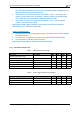
1.2.4. On-board PCB Antenna
HF-LPT120A module suppo rt internal on-board PCB antenna option. When cus tomer select internal
antenna, you shall comply with following antenna design rules and module location suggestions:
For customer PCB, R ED color region (8x10mm) can’t put co mponet or paste GND net;
Antenna must away from metal or high components at least 10mm;
Antenna can’t be shielded by a ny metal enclosure;
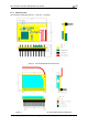
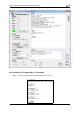
Figure 4. Suggested Module Placement Region
High-Flying suggest HF-LPB100 module better locate in following region at customer board, which to
reduce the effect to antenna and wireless signal, and better consult High-Flying tec hnical people when
you structure your module placement and PCB layout.
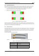
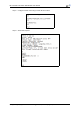
1.2.5. External Antenna
HF-LPT120A supports two way o f external antenna as the following picture show, The I-PEX interface
or the PAD interface(remove the I-PEX connector). The user may choose one of them. If user select
external antenna, HF-LPT120A modules must be connected to the 2.4G antenna a ccording to IEEE
802.11b/g/n standards.
The antenna parameters required as follows:
Figure 5. HF-LPT120A External Antenna picture
Table 5 HF-LPT120A Extern al Antenna Parameters
Item Parameters
Frequency range 2.4~2.5GHz
Impedance 50 Ohm
VSWR 2 (Max)
Return Loss -10dB (Max)
Connector Type I-PEX or populate directly