
User's Manual
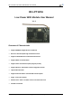


HF-LPT120A Low Power WiFi Module User Manual
Shanghai High-Flying Electronics Technology Co., Ltd(www.hi-flying.com) -10-
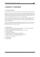
1.2. Hardware Introduction
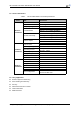
1.2.1. Pins Definition
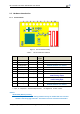
Figure 1. HF-LPT120A Pins Map
Table 2 HF-LPT120A Pins Definition
Pin Description Net Name Signal
Type
Comments
1 Ground GND Power
2 +3.3V Power DVDD Power 3.3V@300m
A
3Restore
Configuration
nReload I/O,PU Can be configured a s GPIO_2
Detailed functions see <Notes>
4 Module Reset EXT_RESETn I,PU “Low” effective r eset input.
5 UART0 UART0_RX I GPIO_19
6 UART0 UART0_TX O,PU GPIO_20
7 GPIO_5 GPIO_5 I/O GPIO_5,UART1_TXD
UART1 Debug Output
8 GPIO_6 GPIO_6 I/O GPIO_6, UART1_RXD
UART1 Debug Input
9 GPIO_3 nReady I/O Can be configured as nReady,GPIO
10 GPIO_15 nLink I/O Can be configured as nLink,GPIO
Detailed functions see <Notes>
I—Input, O—Output,PU—Internal Pullup Resistor; I/O: Digital I/O;Power—Power
<Notes>
nReload Pin (Button) function:
1. When this pin is set to “low” during module boot up, the module will enter wireless
firmware and config upgrade mode. This mode is used for customer manufacture.