
User Manual


High-Flying
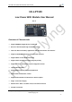
HF-LPB Low Power WiFi Module User Manual
Shanghai High-Flying Electronics Technology Co., Ltd
www.hi-flying.com
- 6 -
LIST OF FIGURES
Figure 1. HF-LPT100 Pins Map ...........................................................................................................11
Figure 2. HF-LPT100 Mechanical Dimension......................................................................................13
Figure 3. HF-LPT100 External Antenna picture ..................................................................................13
Figure 4. HF-LPT100 Evaluation Kit ....................................................................................................14
Figure 5. HF-LPT100 Order Information ..............................................................................................15
Figure 6. HF-LPT100 Hardware Typical Application ...........................................................................15
Figure 7. HF-LPT100 Smart LED Application Hardware Connection..................................................16
Figure 8. HF-LPT100 Basic Wireless Network Structure ....................................................................18
Figure 9. HF-A11 AP+STA Network Structure ....................................................................................19
Figure 10. Socket B function demo ....................................................................................................23
Figure 11. Multi-TCP Link Data Transmition Structure ......................................................................24
Figure 12. Open Web Management page ..........................................................................................25
Figure 13. System Web Page ............................................................................................................26
Figure 14. Work Mode Page ..............................................................................................................26
Figure 15. STA Setting Page .............................................................................................................27
Figure 16. AP Setting Page ...............................................................................................................27
Figure 17. Other Setting Page ...........................................................................................................28
Figure 18. Account Page....................................................................................................................28
Figure 19. Upgrade SW page ............................................................................................................29
Figure 20. Restart Page .....................................................................................................................29
Figure 21. Restore Page ....................................................................................................................30
Figure 22. STA Interface Debug Connection .....................................................................................30
Figure 23. AP Interface Debug Connection .......................................................................................31
Figure 24. “CommTools” Serial Debug Tools ....................................................................................31
Figure 25. “TCPUDPDbg” Tools Create Connection .........................................................................31
Figure 26. “TCPUDPDbg” Tools Setting ............................................................................................32
Figure 27. “TCPUDPDbg” Tools Connection .....................................................................................32
Figure 28. Wireless Control Application .............................................................................................32
Figure 29. Remote Management Application.....................................................................................33
Figure 30. Transparent Serial Port Application ..................................................................................33
Figure 31. HF-LPT100 Default UART Port Parameters .....................................................................34
Figure 32. Switch to Configuration Mode ...........................................................................................34
Figure 33. ”AT+H” Instruction for Help ...............................................................................................35
Figure 34. Reflow Soldering Profile ...................................................................................................59
Figure 35. Shipping Information .........................................................................................................60