
User Manual


High-Flying
HF-LPB Low Power WiFi Module User Manual
Shanghai High-Flying Electronics Technology Co., Ltd
www.hi-flying.com
- 23 -
When module works at PWM mode, PC and other equipts can setup connection (TCP/UDP) through
WiFi, then read/write GPIO/PWM information through command.
GPIO n OUT 0, Set GPIOn as output and output ‘0’, Response GPIO OK or GPIO NOK;
GPIO n OUT 1, Set GPIOn as output and output ‘1’, Response GPIO OK or GPIO NOK;
GPIO n GET, Read GPIOn pin status, Response +ok=1 or GPIO NOK
GPIO n SET, Save GPIOn set, Response GPIO OK or GPIO NOK
PWM n frequency duty, Set PWMn Channel output, Response GPIO OK or GPIO NOK
PWM n GET, Read PWMn Channel set, Response +ok=frequency duty or PWM NOK
PWM n SET, Save PWMn Channel set, Response PWM OK or PWM NOK
Notes: Please refer to Appendix B for details to use GPIO/PWM.
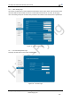
2.8. SOCKET B Function
HF-LPT100 support double socket communication, the socket B function is disabled by
default.
After the module is started, send command “AT+SOCKB” to set the connection parameter,
send command “AT+TCPDISB=on” to try to connect with TCP server, the module will stop
connecting after three failures. Send command “AT+TCPDISB=on” to make connection.
Send command “AT+TCPDISB=off” to close connection. Send command “AT+TCPLKB” to
inqure TCP connection.
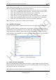
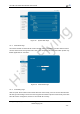
Figure 10. Socket B function demo
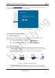
2.9. Multi-TCP Link Connection
When HF-LPT100 module configured as TCP Server, it supports Multi-TCP link connection,
and maximum 5 TCP clients permit to connect to HF-LPT100 module. User can realize multi-
TCP link connection at each work mode.
Multi-TCP link connection will work as following structure: