
User Manual


High-Flying
HF-LPB Low Power WiFi Module User Manual
Shanghai High-Flying Electronics Technology Co., Ltd
www.hi-flying.com
- 16 -
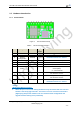
1.3.2. Smart LED Application Hardware Typical Connection
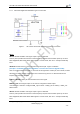
Figure 7. HF-LPT100 Smart LED Application Hardware Connection
Notes:
nReset- Module hardware reset signal. Input. Logics “0” effective.
There is pull-up resister internal and no external pull-up required. When module power up or some
issue happened, MCU need assert nRST signal “0” at least 10ms, then set” 1” to keep module fully
reset.
nReload- Module restore to factory default configuration.Input. Logics “0” effective.
(This pin is recommend to connect to button, is used to enter wireless upgrade mode)
User can de-assert nReload signal “0” more than 3s through button or MCU pin, then release, module
will restore to factory default configuration and re-start boot up process.. If nReload function not
required, can leave this pin open.
UART0_TXD/RXD- UART port data transmit and receive signal.
PWM-n- PWM control signal output. It can also be configured as GPIO output.
“AT+LPTIO=on” command configure PWM_1 pin as nLink、PWM_2 pin as nReady、PWM_3 as
WPS function.
nReset- Module hardware reset signal. Input. Logics “0” effective.
There is pull-up resister internal and no external pull-up required. When module power up or some
issue happened, MCU need assert nRST signal “0” at least 10ms, then set” 1” to keep module fully
reset.