
User Manual


High-Flying
HF-LPB Low Power WiFi Module User Manual
Shanghai High-Flying Electronics Technology Co., Ltd
www.hi-flying.com
- 11 -
1.2. Hardware Introduction
1.2.1. Pins Definition
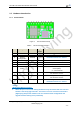
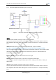
Figure 1. HF-LPT100 Pins Map
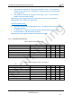
Table 2 HF-LPT100 Pins Definition
Pin
Description
Net Name
Signal
Type
Comments
1
Ground
GND
Power
2
+3.3V Power
DVDD
Power
3.3V@250mA
3
Restore
Configuration
nReload
I,PU
Detailed functions see <Notes>
4
Module Reset
EXT_RESETn
I,PU
“Low” effective reset input.
5
UART0
UART0_RX
I
GPIO5, No connect if not use.
6
UART0
UART0_TX
O
GPIO6, No connect if not use.
7
Power Control
Switch
PWR_SW
I,PU
“0” – Power Down Mode(Lowest Power
Consumption)
“1” – Normal mode
8
PWM Channel 3
PWM_3
I/O
Can be configured as WPS/GPIO18
No connect if not use.
9
PWM Channel 2
PWM_2
I/O
Can be configured as nReady/GPIO12.
No connect if not use.
10
PWM Channel 1
PWM_1
I/O
Can be configured as nLink/GPIO11.
Detailed functions see <Notes>
<Notes>
nReload Pin (Button) function:
1. When this pin is set to “low” during module boot up, the module will enter wireless
firmware and config upgrade mode. This mode is used for customer manufacture.
(High-Flying will provide software tools for customer batch configuration and
upgrade firmware during mass production)