HF-LPB Low Power WiFi Module User Manual HF-LPT100 Low Power WiFi Module User Manual in g V 1.3 ly Overview of Characteristic Support IEEE802.
HF-LPB Low Power WiFi Module User Manual TABLE OF CONTENTS LIST OF FIGURES ...................................................................................................................................6 LIST OF TABLES ....................................................................................................................................7 HISTORY ..................................................................................................................................................
HF-LPB Low Power WiFi Module User Manual 3.1.7. Account Management Page .............................................................................................28 3.1.8. Upgrade Software Page ...................................................................................................29 3.1.9. Restart Page .....................................................................................................................29 3.1.10. 3.2. HF-LPT100 Usage Introduction ........................
HF-LPB Low Power WiFi Module User Manual AT+ TCPLK ...............................................................................................................44 4.2.2.26. AT+ TCPTO ...............................................................................................................45 4.2.2.27. AT+TCPDIS ...............................................................................................................45 4.2.2.28. AT+SOCKB ......................................................
HF-LPB Low Power WiFi Module User Manual 4.2.2.68. 5. AT+LPTIO..................................................................................................................57 PACKAGE INFORMATION ........................................................................................................59 5.1. Recommended Reflow Profile ..............................................................................................59 5.2. Device Handling Instruction (Module IC SMT Preparation) ...........
HF-LPB Low Power WiFi Module User Manual LIST OF FIGURES HF-LPT100 Pins Map ...........................................................................................................11 Figure 2. HF-LPT100 Mechanical Dimension......................................................................................13 Figure 3. HF-LPT100 External Antenna picture ..................................................................................13 Figure 4. HF-LPT100 Evaluation Kit .........................
HF-LPB Low Power WiFi Module User Manual LIST OF TABLES Table 1 HF-LPT100 Module Technical Specifications .......................................................................10 Table 2 HF-LPT100 Pins Definition ....................................................................................................11 Table 3 Absolute Maximum Ratings: ......................................................................................................12 Table 4 Power Supply & Power Consumption: .........
HF-LPB Low Power WiFi Module User Manual HISTORY Ed. V1.0 08-01-2013 First Version. Ed. V1.1 09-11-2013 Update AT command. Ed. V1.2 10-12-2013 Update AT command. Update PWM/GPIO function. Add HTTP protocol demo. Add auto-frame function. Ed. V1.3 10-18-2013 Add nReload Pin wireless upgrade and config description, add nLink Pin H ig h- Fl yi ng wireless upgrade indication description. Shanghai High-Flying Electronics Technology Co., Ltd www.hi-flying.
HF-LPB Low Power WiFi Module User Manual 1. PRODUCT OVERVIEW 1.1. General Description The HF-LPT100 is a fully self-contained small form-factor, single stream, 802.11b/g/n Wi-Fi module, which provide a wireless interface to any equipment with a Serial/SPI/USB interface for data transfer.
HF-LPB Low Power WiFi Module User Manual 1.1.2 Device Paremeters Table 1 Parameters Certification Wireless standard Frequency range FCC/CE 802.11 b/g/n 2.412GHz-2.484GHz 802.11b: +16 +/-2dBm (@11Mbps) 802.11g: +14 +/-2dBm (@54Mbps) 802.11n: +13 +/-2dBm (@HT20, MCS7) 802.11b: -93 dBm (@11Mbps ,CCK) 802.11g: -85 dBm (@54Mbps, OFDM) 802.11n: -82 dBm (@HT20, MCS7) External:I-PEX Connector External:Pad connector UART PWM, GPIO 2.8~3.6V Peak [Continuous TX]: ~200mA Normal [WiFi ON/OFF, DTIM=100ms]: Average.
HF-LPB Low Power WiFi Module User Manual 1.2. Hardware Introduction Pins Definition ng 1.2.1. Table 2 Description 1 2 3 Ground +3.3V Power Restore Configuration Module Reset UART0 UART0 Power Control Switch Net Name GND DVDD nReload Signal Type Power Power I,PU EXT_RESETn UART0_RX UART0_TX PWR_SW I,PU I O I,PU H ig h- 4 5 6 7 HF-LPT100 Pins Definition Comments Fl Pin HF-LPT100 Pins Map yi Figure 1.
HF-LPB Low Power WiFi Module User Manual 2. After module is powered up, short press this button ( “Low” < 3s ) to make the module go into “Smart Link “ config mode, waiting for APP to set password and other information. 3. After module is powered up, long press this button ( “Low” > 3s ) to make the module recover to factory setting. High-Flying strongly suggest customer fan out this pin to connector or button for “Manufacture” and “ Smart Link” application. nLink Pin (LED) function: 1.
HF-LPB Low Power WiFi Module User Manual 1.2.3. Mechanical Size H ig h- Fl yi ng HF-LPT100 modules physical size (Unit: mm) as follows: Figure 2. 1.2.4. HF-LPT100 Mechanical Dimension External Antenna HF-LPT100 supports two way of external antenna as the following picture show, The IPEX interface or the PAD interface. The user may choose one of them. If user select external antenna, HF-LPT100 modules must be connected to the 2.4G antenna according to IEEE 802.11b/g/n standards.
HF-LPB Low Power WiFi Module User Manual Table 5 1.2.5. HF-LPT100 External Antenna Parameters Item Parameters Frequency range 2.4~2.5GHz Impedance VSWR Return Loss Connector Type 50 Ohm 2 (Max) -10dB (Max) I-PEX or populate directly Evaluation Kit ng High-Flying provides the evaluation kit to promote user to familiar the product and develop the detailed application.
HF-LPB Low Power WiFi Module User Manual 1.2.6. Order Information Base on customer detailed requirement, HF-LPT100 series modules provide different variants and Fl 1.3. Typical Application Hardware Typical Application H ig h- 1.3.1. HF-LPT100 Order Information yi Figure 5. ng physical type for detailed application. Figure 6. HF-LPT100 Hardware Typical Application Shanghai High-Flying Electronics Technology Co., Ltd www.hi-flying.
HF-LPB Low Power WiFi Module User Manual Smart LED Application Hardware Typical Connection Notes: HF-LPT100 Smart LED Application Hardware Connection Fl Figure 7. yi ng 1.3.2. nReset- Module hardware reset signal. Input. Logics “0” effective. There is pull-up resister internal and no external pull-up required. When module power up or some H ig h- issue happened, MCU need assert nRST signal “0” at least 10ms, then set” 1” to keep module fully reset.
HF-LPB Low Power WiFi Module User Manual nLink- Module WIFI connection status indication. Output. (This pin is recommend to connect to LED, indicate status when the module in wireless upgrade mode) When module connects to AP (AP associated), this pin will output “0”. This signal used to judge if module already at WiFi connection status. Thers is pull-up resister internal and no external pull-up H ig h- Fl yi ng required. If nLink function not required, can leave this pin open.
HF-LPB Low Power WiFi Module User Manual 2. FUNCTIONAL DESCRIPTION 2.1. Wireless Networking HF-LPT100 module can be configured as both wireless STA and AP base on network type. Logically there are two interfaces in HF-LPT100. One is for STA, and another is for AP. When HF-LPT100 works as AP, other STA equipments are able to connect to wireless LAN via HF-LPT100 module. Notes: ng Wireless Networking with HF-LPT100 is very flexible.
Figure 9. ng HF-LPB Low Power WiFi Module User Manual HF-A11 AP+STA Network Structure When module enables AP+STA function, Module’s STA interface can connect with router and connect yi to TCP server in the network.
HF-LPB Low Power WiFi Module User Manual TCP/UDP Linking Parameters Protocol Type Link Type(Server or Client) Target Port ID Number Target Port IP Address Serial Port Parameters Baud Rate Data Bit Parity (Check) Bit Stop Bit Hardware Flow Control ng 2.3. UART Frame Scheme 2.3.1. UART Free-Frame HF-LPT100 support UART free-frame function. If user select open this function, module will check the yi intervals between any two bytes when reciving UART data.
HF-LPB Low Power WiFi Module User Manual 2.4. Encryption Encryption is a method of scrambling a message that makes it unreadable to unwanted parties, adding a degree of secure communications. There are different protocols for providing encryption, and WEP WPA-PSK/TKIP WPA-PSK/AES WPA2-PSK/TKIP WPA2-PSK/AES ng the HF-LPT100 module supports following: 2.5. Parameters Configuration HF-LPT100 module supports two methods to configuration parameters: Web Accessing and AT+instruction set.
HF-LPB Low Power WiFi Module User Manual AT+UPCFG command to start remote Factory Config upgrade. After excuate this command, the module will firstly download configuration file (“config.txt”), then download the upgrade file base on the CFG address listed in the configure file. AT+UPNVR command to start remote NVRAM Data upgrade. After excuate this command, the module will firstly download configuration file (“config.txt”), then download the upgrade file base on the NVR address listed in the configure file.
HF-LPB Low Power WiFi Module User Manual When module works at PWM mode, PC and other equipts can setup connection (TCP/UDP) through WiFi, then read/write GPIO/PWM information through command.
HF-LPB Low Power WiFi Module User Manual yi ng Upstream: All dates from different TCP connection or client will be transmitted to the serial port as a sequence. Downstream: All data from serial port (user) will be duplicate and broadcast to every TCP connection or client. Detailed multi-TCP link data transmition structure as following figure: H ig h- Fl Figure 11. Multi-TCP Link Data Transmition Structure Shanghai High-Flying Electronics Technology Co., Ltd www.hi-flying.
HF-LPB Low Power WiFi Module User Manual 3. OPERATION GUIDELINE 3.1. Configuration via Web Accessing When first use HF-LPT100 modules, user may need some configuration. User can connect to HFLPT100 module’s wireless interface with following default setting information and configure the module through laptop. HF-LPT100 Web Access Default Setting Default Setting HF-LPB100 IP Address 10.10.100.254 Subnet Mask 255.255.255.
ng HF-LPB Low Power WiFi Module User Manual 3.1.3. Work Mode Page yi Figure 13. System Web Page HF-LPT100 module can works at AP mode to simplify user’s configuration, can also works at STA to connect remote server through AP router. Also, it can configure at AP+STA mode which provide very H ig h- Fl flexible application for customers. Figure 14. Work Mode Page 3.1.4.
ng HF-LPB Low Power WiFi Module User Manual 3.1.5. AP Setting Page yi Figure 15. STA Setting Page When user select module works at AP and AP+STA mode, then need setting this page and provide Fl wireless and network parameters. Most of the system support DHCP to achieve IP address, so we H ig h- suggest to “Enable” DHCP server in most applications. Figure 16. AP Setting Page Shanghai High-Flying Electronics Technology Co., Ltd www.hi-flying.
HF-LPB Low Power WiFi Module User Manual 3.1.6. Other Setting Page HF-LPT100 usually works at data transparent transmission mode. At this mode, the user device which connected with HF-LPT100 will connect and communicate with remote PC or server. At this page, yi ng user need setting serial port communication parameters and defines TCP related protocal parameters. 3.1.7. Fl Figure 17. Other Setting Page Account Management Page H ig h- This page set web server’s user name and password. Figure 18.
HF-LPB Low Power WiFi Module User Manual 3.1.8. Upgrade Software Page yi ng User can upgrade new software (firmware) version through Wi-Fi. 3.1.9. Restart Page Fl Figure 19. Upgrade SW page Most of the settting and configuration can only effective after system restart. User shall restart after H ig h- finish all setting. Figure 20. Restart Page 3.1.10. Restore Page After module restore factory default setting, all user configuration profile will lose.
HF-LPB Low Power WiFi Module User Manual User can access http://10.10.100.254 to set again, and user name and password is “admin”. HF- ng LPT100 will restore to AP mode for factory default setting. yi Figure 21. Restore Page 3.2.1. Software Debug Tools Fl 3.2. HF-LPT100 Usage Introduction High-Flying use two common software tools debugging and applying HF-LPT100 module. (User can also select other tools used to debug serial port). Serial Debugging Software: ComTools H ig h- 3.2.2.
HF-LPB Low Power WiFi Module User Manual Figure 23. AP Interface Debug Connection 3.2.4. Default Parameter Setting Default SSID: HF-LPB100; Deault security mode: open,none; User UART parameter setting:115200,8,1,None; Default network parameter setting:TCP,Server,8899,10.10.100.254; Module IP address: dhcp,0.0.0.0,0.0.0.0,0.0.0.0; Module Debug ng 3.2.3. H ig h- Fl and open serial port connection.
HF-LPB Low Power WiFi Module User Manual Figure 26. ng Then setting the TCP/UDP connection parameters. Default as following: “TCPUDPDbg” Tools Setting H ig h- Fl yi Then, click “Create” button to create a connection. Figure 27. “TCPUDPDbg” Tools Connection Now, in transparent transmission mode, data can be transferred from “CommTools” program to “TCPUDPDbg” program, or in reverse. You can see data in receiver side will keep same as in sender side. 3.3. Typical Application Examples 3.3.1.
HF-LPB Low Power WiFi Module User Manual For this wireless control application, HF-LPT100 works as Ad-Hoc mode. Module’s serial port connects to user device. So, control agent (Smart phone for this example) can manage and control the user device through the wireless connection with HF-LPT100 module. Remote Management Application ng 3.3.2. Figure 29. Remote Management Application yi For this remote management application, HF-LPT100 works as STA mode and connects to Internet through wireless AP.
HF-LPB Low Power WiFi Module User Manual 4. AT+INSTRUCTION INTRODUCTION 4.1. Configuration Mode When HF-LPT100 power up, it will default works as transparent transmission mode, then user can switch to configuration mode by serial port command. HF-LPT100 UART default parameters setting as ng below figure, Figure 31. HF-LPT100 Default UART Port Parameters page setting function. 4.1.1.
HF-LPB Low Power WiFi Module User Manual 4.2. AT+ Instruction Set Overview User can input AT+ Instruction through hyper terminal or other serial debug terminal, also can program the AT+ Instruction to script. User can also input “AT+H” to list all AT+ Instruction and description to Fl yi ng start. H ig h- Figure 33. ”AT+H” Instruction for Help 4.2.1. Instruction Syntax Format AT+Instruction protocol is based on the instruction of ASCII command style, the description of syntax format as follow.
HF-LPB Low Power WiFi Module User Manual Notes: When input AT+Instruction, “AT+” character will display capital letter automatic and other parts will not change as you input.
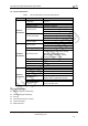
HF-LPB Low Power WiFi Module User Manual H ig h- Fl yi ng CFGFR Batch Read Factory Default Configure Parameters CFGTF Copy User Parameters to Factory Default Parameters UART Instruction Set UART Set/Query serial port parameters UARTFT Open/Close UART auto-frame function UARTFT Set/Query UART auto-frame trigger time UARTFL Set/Query UART auto-frame trigger length UARTTE Set/Query UART free-frame triggerf time between two bytes Command Mode Set SEND Send Data at Command Mode RECV Receive Data at Command
HF-LPB Low Power WiFi Module User Manual yi ng UPAUTO Start remote upgrade LOGSW Open/Close remote upgrade log LOGPORT Set/Query UDP port of remote upgrade log UPST Start remote Application upgrade Power Management Instruction Set MSLP Set/Query deep sleep/standby mode parameters Network Time Set NTPRF Set/Query time calibration interval NTPEN Enable/Disable time calibration function NTPTM Query time Others Instruction Set WRMID Set module ID RLDEN Set/Query GPIO45 status ASWD Set/Query WiFi configuratio
HF-LPB Low Power WiFi Module User Manual AT+ENTM +ok< LF >< LF > When operate this command, module switch from configuration mode to transparent transmission mode. 4.2.2.4. AT+TMODE Function: Set/Query module data transfer mode. Format: Query Operation +ok=< LF >< LF > Set Operation AT+TMODE= +ok< LF >< LF > Parameters: tmode: data transfer mode, include: throughput cmd pwm yi Fl 4.2.2.5.
HF-LPB Low Power WiFi Module User Manual AT+ RELD +ok=rebooting…< LF >< LF > When operate this command, module will restore to factory default setting and reboot. 4.2.2.8. AT+FCLR Function: Erase factory setting; Format: Query Operation AT+FCLR ng +ok=< LF >< LF > 4.2.2.9. AT+Z Function: Re-start module; Format: AT+ Z Function: Help; Format: Query Operation AT+H Fl yi 4.2.2.10.
HF-LPB Low Power WiFi Module User Manual 4.2.2.13. AT+CFGFR Function: Batch Read Factory Default Configure Parameters; Format: Query Operation AT+CFGFR +ok=< LF >< LF > Parameters: config: the first two bytes means the length of configuration parameters; 4.2.2.14. AT+CFGTF Function: Copy User Parameters to Factory Default Parameters; Format: Query Operation AT+CFGTF +ok=< LF >< LF > Parameters: status: feedback operation status; yi 4.
HF-LPB Low Power WiFi Module User Manual 4.2.2.16. AT+ UARTF Function: Open/Close UART auto-frame function; Format: Query Operation AT+ UARTF +ok=< LF >< LF > Set Operation AT+ UARTF= +ok< LF >< LF > Parameters: para: ng disable - Close auto-frame function; enable - Open auto-frame function; 4.2.2.17.
HF-LPB Low Power WiFi Module User Manual +ok=< LF >< LF > Set Operation AT+ UARTTE= +ok< LF >< LF > Parameters: mode: fast: free-frame trigger time between two bytes is 10ms; normal: free-frame trigger time between two bytes is 50ms; Function: Send Data at Command Mode. Format: AT+SEND= +ok< LF >< LF > Parameters: ng 4.2.2.20. AT+ SEND data_lenth: Lenth of send data.
HF-LPB Low Power WiFi Module User Manual Format: Query Operation AT+NETP +ok=< LF >< LF > Set Operation AT+NETP= +ok< LF >< LF > Parameters: protocol: TCP UDP ng CS: Network mode: SERVER CLIENT Port: protocol port ID: Decimal digit and less than 65535 IP: Server’s IP address when module set as client yi If set as UDP SERVER, the module will save the IP address and port of the latest UDP packet rec
HF-LPB Low Power WiFi Module User Manual on: TCP link setup; off: TCP link not setup; 4.2.2.26. AT+ TCPTO Function: Set/Query TCP timeout; Format: Query Operation AT+ TCPTO +ok=
HF-LPB Low Power WiFi Module User Manual +ok< LF >< LF > Parameters: Protocol: Protocol type: TCP: Only for TCP Client UDP Port: Protocol Port in decimal, less than 65535 IP: Destination IP address, domain name is support Function: Open/Close TCP_B connection Format: Query Operation AT+TCPDISB +ok=< LF >< LF > Set Operation AT+ TCPDISB = Parameters: yi +ok< LF >< LF > ng 4.2.2.29.
HF-LPB Low Power WiFi Module User Manual +ok=< LF >< LF > Parameters: sta.: TCP_B connection status on: TCP connected off: TCP disconnected 4.2.2.32. AT+SNDB Function: Send datas to SOCKB at Command Mode Format: AT+SNDB= ng +ok< LF >< LF > Parameters: data_lenth: Lenth of send data. Range: 0~1000 Byte The UART port will wait 3 seconds for input after this command is sent OK. The data received from UART port is sent to socket.
HF-LPB Low Power WiFi Module User Manual +ok=< LF >< LF > Set Operation AT+ WSKEY=< auth,encry,key> +ok< LF >< LF > Parameters: auth: Authentication mode OPEN SHARED WPAPSK WPA2PSK encry:Encryption algorithm NONE: When “auth=OPEN”, effective WEP: When “auth=OPEN” or “SHARED”, effective TKIP: When ”auth= WPAPSK” or “WPA2PSK”, effective AES: When “auth= WPAPSK” “WPA2PSK”, effective key: password, ASCII code, shall less than 64 bit
HF-LPB Low Power WiFi Module User Manual Parameters: code: security code 8888 (default value) Mac_address: STA MAC address, such as ACCF23FF1234 4.2.2.38. AT+ WSLK Function: Query STA WiFi link status Format: Query Operation +ok=< LF >< LF > Parameters: ret ”Disconnected”, if no WiFi connection; ”AP’ SSID(AP’s MAC” ), if WiFi connection available; ”RF Off”, if WiFi OFF; 4.2.2.39.
HF-LPB Low Power WiFi Module User Manual +ok< LF >< LF > Parameters: address: STA’s DNS server address; Effective right away. 4.2.2.42. AT+ LANN Function: Set/Query AP’s network parameters; Format: Query Operation AT+LANN Set Operation AT+ LANN=< ipaddress,mask> +ok< LF >< LF > Parameters: ipaddress: AP’s IP address; mask: AP’s net mask; 4.2.2.43.
HF-LPB Low Power WiFi Module User Manual AT+ WAKEY=< auth,encry,key> +ok< LF >< LF > Parameters: auth: include OPEN WPA2PSK Encry: include NONE: When “auth=OPEN” available; AES: When “auth=WPA2PSK” available; key: security code, ASCII code, smaller than 64bit and bigger than 8 bit; ng 4.2.2.45.
HF-LPB Low Power WiFi Module User Manual AT+ WADMN = +ok< LF >< LF > Parameters: Domain_name: Webpage domain name (within 20 characters, can’t all numbers). 4.2.2.48. AT+PLANG Function: Set/ Query webpage language option; Format: Query Operation +ok= < LF >< LF > Set Operation AT+ PLANG= +ok< LF >< LF > Parameters: language: webpage’s language CN: Chinese Version (Default); EN: English Version; 4.2.2.49.
HF-LPB Low Power WiFi Module User Manual filename: the upgrade configure file name (within 20 characters). 4.2.2.51. AT+UPWEB Function: Remote webpage upgrade Format: Query Operation AT+UPWEB +ok=< LF >< LF > Parameters: log: Some status print log from remote upgrade. on the setting of UPURL, UPFILE command contents; 4.2.2.52.
HF-LPB Low Power WiFi Module User Manual Note: After execute this command, the HF-LPT100 will automatic start upgrade Application, Webpage, factory setting base on the setting of UPURL, UPFILE command contents; 4.2.2.55. AT+LOGSW Function: Open/Close remote upgrade logfile Format: Query Operation AT+LOGSW +ok=< LF >< LF > Set Operation ng AT+LOGSW= +ok< LF >< LF > Parameters: status: on: Open.
HF-LPB Low Power WiFi Module User Manual Query Operation AT+ WEBU +ok= < LF >< LF > Set Operation AT+ WEBU= +ok< LF >< LF > Parameters: username: User Name, within 15 characters, not support empty. password: password, within 15 characters, support empty. ng 4.2.2.59.
HF-LPB Low Power WiFi Module User Manual +ok=< LF >< LF > Set Operation AT+ NTPEN= +ok< LF >< LF > Parameters: status:status of time calibration on:Enable time calibration off:Disable time calibration Function: Query network time Format: Query Operation AT+ NTPTM +ok=
HF-LPB Low Power WiFi Module User Manual Format: Query Operation AT+ ASWD +ok= < LF >< LF > Set Operation AT+ ASWD= < LF >< LF > Parameters: aswd: WiFi Configuration Password (within 20 characters). Function: Set Wi-Fi Auto Switch Function Format: Query Operation AT+ MDCH +ok= < LF >< LF > Set Operation ng 4.2.2.66.
HF-LPB Low Power WiFi Module User Manual Format: Query Operation AT+LPTIO +ok=< LF>< LF> Set Operation AT+LPTIO= +ok< LF>< LF> Parameters: staus: Enable/Disable nReady、nLink function. PWM_1 pin is for nLink function, PWM_2 pin is for nReady function. on:Enable nReady、nLink function off:Disable nReady、nLink function H ig h- Fl yi ng Shanghai High-Flying Electronics Technology Co., Ltd www.hi-flying.
HF-LPB Low Power WiFi Module User Manual 5. PACKAGE INFORMATION ng 5.1. Recommended Reflow Profile yi Figure 34. Reflow Soldering Profile Table 11 Reflow Soldering Parameter Item Temperature (Degree) 1 Reflow Time 2 Peak-Temp Fl NO. Time of above 220 Time(Sec) 35~55 sec 260 max H ig h- Note: 1. Recommend to supply N2 for reflow oven. 2. N2 atmosphere during reflow (O2<300ppm) 5.2. Device Handling Instruction (Module IC SMT Preparation) 1.
HF-LPB Low Power WiFi Module User Manual 5.3. Shipping Information TRAY BOX Size: 422*247*72 mm (inside) ng Size: 420*245*34 mm CARTON H ig h- Fl yi Size: 440*260*320 mm (inside) Figure 35. Shipping Information Note: 1 tray = 5*20pcs = 100 pcs 1 box = 2 trays = 2 * 100 pcs = 200pcs 1 carton = 4 boxes = 4 * 200 pcs = 800pcs Shanghai High-Flying Electronics Technology Co., Ltd www.hi-flying.
HF-LPB Low Power WiFi Module User Manual H ig h- Fl yi ng APPENDIX A: HW REFERENCE DESIGN Detailed HF-LPT100 Evluation Board design source files, pls access High-Flying web download page or contact with High-Flying technical support people to acquire. Shanghai High-Flying Electronics Technology Co., Ltd www.hi-flying.
HF-LPB Low Power WiFi Module User Manual APPENDIX B: CONTROL GPIO/PWM FUNCTION WITH NETWORK COMMANDS Send command data to control module’s GPIO, PWM port after make network connection with B.1 Network Command GPIO OUT Function: Set GPIO Channel value temporarily.
HF-LPB Low Power WiFi Module User Manual GPIO NOK: Command failed GPIO SET Function: Save GPIO Channel setting Parameters: channel:GPIO Channel number,it can be 11、12、18(GPIO Pin Number ) Return Data: GPIO OK: Command successful GPIO NOK: Command failed H ig h- Fl B.1.3 yi ng B.1.
PWM GET Function: Query PWM Channel output Parameters: channel: PWM Channel number,it can be 11、12、18(GPIO Pin Number ) Return Data: +ok= frequency:PWM Channel frequency duty:PWM Channel duty H ig h- Fl B.1.5 yi ng HF-LPB Low Power WiFi Module User Manual PWM NOK: Command failed Shanghai High-Flying Electronics Technology Co., Ltd www.hi-flying.
HF-LPB Low Power WiFi Module User Manual B.1.6 PWM SET Function: Save PWM Channel setting Parameters: channel:PWM Channel number, it can be 11、12、18、20(GPIO Pin number) Return Data: PWM OK: Command successful PWM NOK: Command failed Send hexadecimal data to fastly read module’s port status.
HF-LPB Low Power WiFi Module User Manual value1: Duty of PWM Channel Return Data:【a2 】 Channel:PWM Channel number value1: Duty of PWM Channel Save Present GPIO,PWM Setting Send Data:【7a】: Return Data:【fa】 Read Resources of module Send Data:【7e】: Return Data:【fe 】 value1: Module’s GPIO ouput pin number . value2:Module’s GPIO input pin number value3:Module’s PWM pin number H ig h- Fl yi B.2.
HF-LPB Low Power WiFi Module User Manual APPENDIX C: HTTP PROTOCOL TRANSFER HF-LPT100 module support http data transfer in command mode. If any detailed HTTP protocol, contact us and we may support customization. C.1. HTTP AT command AT+ HTTPURL Function:Set /Query HTTP server IP address and Port Number. Format: Query Operation AT+HTTPURL +ok=< LF >< LF > Set Operation AT+HTTPURL= +ok< LF >< LF > Parameters: IP:IP address. Port:Port number.
HF-LPB Low Power WiFi Module User Manual Parameters: C.1.4. Path:Max length is 50 bytes. AT+ HTTPCN Function:Set/Query Connection of HTTP protocol header Format: Query Operation AT+HTTPCN +ok=< LF >< LF > Set Operation AT+HTTPCN= +ok< LF >< LF > Parameters: AT+ HTTPUA Function:Set/Query User-Agent of HTTP protocol header. Format: Query Operation AT+HTTPUA yi C.1.5. Connection:Max length is 20 bytes.
HF-LPB Low Power WiFi Module User Manual AT+HTTPUA= lwip1.3.2 Set HTTP User-Agent area If send “AT+HTTPDT”, the data packet will be sent as the following instance including the two new line: POST /abcd HTTP/1.1 Connection:keep-alive User-Agent:lwip1.3.2 Content-Length:0 Host:192.168.0.127:8999 ng If send AT+HTTPDT=abcd, the data packet will be sent as the following instance: POST /abcd HTTP/1.1 Connection:keep-alive User-Agent:lwip1.3.2 Content-Length:4 abcd yi Host:192.168.0.
HF-LPB Low Power WiFi Module User Manual APPENDIX D: CONTACT INFORMATION ng -----------------------------------------------------------------------------------------------------------Address: Room.511/510, Building 7, No.365, Chuanhong Road, Pudong New Area, Shanghai, China, 201202 Web: www.hi-flying.com Service Online: 400-189-3108 Sales Contact: sales@hi-flying.
FCC STATEMENT 1. This device complies with Part 15 of the FCC Rules. Operation is subject to the following two conditions: (1) This device may not cause harmful interference. (2) This device must accept any interference received, including interference that may cause undesired operation. 2. Changes or modifications not expressly approved by the party responsible for compliance could void the user's authority to operate the equipment.