
User's Manual
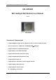

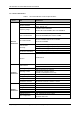
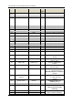
Table Of Contents

HF-LPD100 Low Power WiFi Module User Manual
<Notes>
I — Input;O — Output
PU—Internal Resistor Pull Up; I/O: Digital I/O; Power—Power
Supply nReload Pin (Button) function:
1. When this pin is set to “low” during module boot up, the module will enter wireless
firmware and config upgrade mode. This mode is used for customer manufacture.(See
Appendix to d
ownload software tools for customer batch configuration and upgrade
firmware during mass production)
2. After module is powered up, short press this button (0.2s < “Low” < 1.5s)
and loose to make
the module go into SmartLink V8 config mode, when in SmartLink V8 config mode and short
press this button again to go into SmartAPLink config mode, waiting for APP to set router
SSID and password, config module connect to router. Recommend to use SmartAPLink
method config.
See Appendix to download SmartLink V8 and SmartAPLink APP
3. After module is powered up, long press this button ( “Low” > 4s ) and loose to make the
module recover to factory s
etting.
High-Flying strongly suggest customer fa
n out this pin to connector or button for
“Manufacture” upgrade or “ SmartLink” application.
nReady Pin (LED) function(Low effective):
1. OS initial finished indicator. Only after this pin output low, can the UART function be used.
nLink Pin (LED) function(Low effective):
1.
At wireless firmware and config upgrade mode , this LED used to indicate configure and
upgrade status.
2. At “SmartLink” config mode, this LED is used to indicate APP to finish setting.
3.
At normal mode, it’s Wi-Fi link status indicator. Output Low when STA
mode connect to
router AP or other STA connect to it when in AP mode.
High-Flying strongly suggest customer fan out this pin to LED.
UART1 Debug :
1.
Is used for debug log
High-Flying Electronics Technology Co., Ltd.(www.hi-flying.com)