
User Manual

HF-LPB200 Low Power WiFi Module User Manual
Shanghai High-Flying Electronics Technology Co., Ltd
www.hi-flying.com
- 26 -
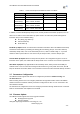
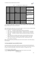
Table 7 HF-LPB200 GPIO Pin Mapping Table
User need get HF-LPB200 SDK to configure these GPIOs to different functions. Please contact high-
flying technical people to acquire more information.
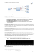
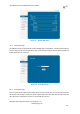
When module works at GPIO mode, PC and other equipts can setup connection (TCP/UDP) through
Wi-Fi, then read/write GPIO information through command.
GPIO n IN, Set GPIOn as input, Response GPIO OK or GPIO NOK;
GPIO n OUT 0, Set GPIOn as output and output „0‟, Response GPIO OK or GPIO NOK;
GPIO n OUT 1, Set GPIOn as output and output „1‟, Response GPIO OK or GPIO NOK;
GPIO n SW, Set GPIOn as output and switch the output status, Response GPIO OK or
GPIO NOK;
GPIO n PWM m1 m2, Set GPIOn output a wave: m1 is „high‟ duration and m2 is ‟low‟
duration (Time unit is „ms‟ and minimal is 10ms), Response GPIO OK or GPIO NOK;
GPIO n GET, Read GPIOn status, Response I0,I1,O0,O1, means”input low”,”input
high”,”output low”,”output high”
Notes: Some SW version may not include these GPIO command set.please contact with high-flying
technical people.
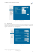
3.10. Analog Digital Converter (ADC) Function
HF-LPB200 integrate two identical ADCs (ADC0 and ADC1) which be programmed separately.The
ADC is a second oeder sigma-delta converter with up to 16-bit resolution. The conversion results can
be written to memory through DMA. Several modes of operation are available for the ADC.
The main features of ADC are follows:
Selectable decimation rates with also set the effective resolution 910 to 16 bits);
GPIO
Function 1
Function 2
Default Setting
Describtion
GPIO7
Sleep_RQ
GPIO
Sleep_RQ
Sleep Control
Function Pins
GPIO8
Sleep_ON
GPIO
Sleep_ON
GPIO10
WPS
GPIO
WPS
WPS functional pin
GPIO11
A/D Input 1
GPIO
GPIO11
16-Bits ADC input pins
Dual ADC input
GPIO12
A/D Input 2
GPIO
GPIO12
GPIO13
OSC32K_IN
GPIO
GPIO13
External 32.768KHz
RTC clock input option
GPIO14
OSC32K_OUT
GPIO
GPIO14
GPIO18
PWM 1
ADC2 Vfef
GPIO18
PWM functiona pins
output.
GPIO20
PWM 2
GPIO
GPIO20
GPIO23
PWM 3
GPIO
GPIO23
GPIO24
PWM 4
GPIO
GPIO24
GPIO25
I2C_SCL
GPIO
GPIO25
I2C Bus Interface
GPIO26
I2C_SDA
GPIO
GPIO26
GPIO27
SPI_MISO
UART2_TXD
GPIO27
Three Functions:
<1> SPI Master/Slave
<2> UART w flow ctl
<3> I2S Interface
GPIO28
SPI_CLK
UART2_CTS
GPIO28
GPIO29
SPI_CS
UART2_RTS
GPIO29
GPIO30
SPI_MOSI
UART2_RXD
GPIO30