
User Manual

HF-LPB200 Low Power WiFi Module User Manual
Shanghai High-Flying Electronics Technology Co., Ltd
www.hi-flying.com
- 17 -
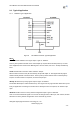
Sleep-RQ- Module Pin Sleep Control. Input.
The user should de-assert this pin low “0”, after 1‟s assert to high ”1” to put the module to sleep status.
Also at the deep sleep/standby mode, user can de-assert this pin low “0”, after 1‟s assert to high ”1” to
put the module to wake up the module.
Sleep-ON- Module Pin Sleep Indicator. Output.
This pin is used to indicate that the module is asleep (Module output “0”) or awake (Module output “1”)
status. If user doesn't use pin sleep function, can leave this pin open.
UART0_TXD/RXD- UART port data transmit and receive signal.
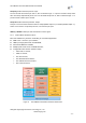
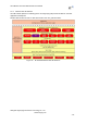
2.2.2. Internal MCU Hardware Feature
MCU and hardware Key Features as following for customized application:
ARM Cortex‐M3 Core, Up to 200Mhz;
1MB in-package QSPI Flash, 512KB SRAM;
SPI Extend 1MB flash available;
Multiple power down mode w/ SRAM Retention;
Configurable GPIO function (Module output);
ADC 16 bit, 2 channel;
PWM, 4 channel;
One I2C interface;
One SPI/I2S/UART interface;
One USB OTG FS2.0 interface;
RTC extend interface;
Figure 9. HF-LPB200 Internal MCU Hardware Architecture