
User Manual

HF-LPB200 Low Power WiFi Module User Manual
Shanghai High-Flying Electronics Technology Co., Ltd
www.hi-flying.com
- 11 -
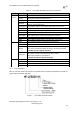
Indicator
“1” – Boot-up No OK;
Also used as hardware watch
dog trigger signal.
No connect if not use.;
45
Restore
Configuration
nReload
I,PU
Module will restore factory
default after set this pin “0” more
than 1s, then set “1”.
46
N.C
No connect
47
Module Reset
EXT_RESETn
I,PU
“Low” effective reset input.
Notes:
1. Detailed GPIO functional application refers ro Chapter 2 “GPIO Function” Section.
2. For customer which plan migrate from HF-LPB to HF-LPB200, please pay attention Pin 35, Pin 46
is NC for HF-LPB200;
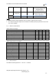
2.1.1. Electrical Characteristics
Absolute Maximum Ratings:
Parameter
Condition
Min.
Typ.
Max.
Unit
Storage temperature range
-45
125
°C
Maximum soldering temperature
IPC/JEDEC J-STD-020
260
°C
Supply voltage
0
3.8
V
Voltage on any I/O pin
0
3.3
V
ESD (Human Body Model HBM)
TAMB=25°C
2
KV
ESD (Charged Device Model, CDM)
TAMB=25°C
500
V
Power Supply & Power Consumption:
Parameter
Condition
Min.
Typ.
Max.
Unit
Operating Supply voltage
2.97
3.3
3.63
V
Supply current, peak
Continuous Tx
200
250
mA
Supply current, IEEE PS
DTIM=100ms
21
mA
Input high voltage
VDD*70%
VDD+0.4
V
Input low voltage
-.04
VDD*30%
V
Input leakage current
VDD On
2
uA
Input capacitance
5
pF
Pullup strength
10
50
uA
Pulldowm strength
10
50
uA
Analog input range
0
3
V
Analog output range
0
3
V
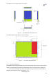
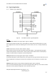
2.1.2. Mechanical Size
HF-LPB200 modules physical size (Unit: mm) as follows: