
User's Manual

HF-L
PB125 Low Power Wi-Fi Module User Manual
Shang
hai High-Flying Electronics Technology Co., Ltd(www.hi-flying.com) -
8
-
1.2.
Hardware Introduction
1.2.1.
Pins Definition
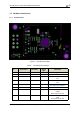
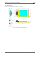
Figure 1
. HF-LPB125 Pins Map
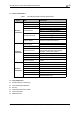
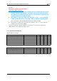
Table 2 HF-LPB125 Pins Definition
Pin Desc
ribtion
Net
Name
Signal
Ty
pe
Commen
ts
1 +5V Power DVDD Power 5V@250m
A
2Gr
ound GNDPower
3 UART0 UART0_RX I,PU 5V, GPIO19. No connect if not
use.
4 UART0 UART0_TX O,PU 5V, GPIO20. No connect if not
use.
5 Multi-Function nReload I,PU 3.3V, GPIO2. Detailed
functions see <Notes>
6 Module Reset EXT_RESETn I,PU 3.3V, “Low” effective reset input.
7 GPIO GPIO5 I/O 3.3V I/O, UART1_TXD debug
output
No connect if not use.
8 GPIO GPIO6 I/O 3.3V I/O, UART1_RXD debug
input
No connect if not use.