
User's Manual

HF-LPB Low Power WiFi Module User Manual
Shanghai High-Flying Electronics Technology Co., Ltd
www.hi-flying.com
- 15 -
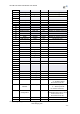
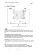
Table 4 HF-LPB Evaluation Kit Interface Description
1.2.6. Order Information
Base on customer detailed requirement, HF-LPB series modules provide different variants and
physical type for detailed application.
Figure 7. HF-LPB Order Information
Function
Name Description
External
Interface
COM1 Main data/command RS-232 interface
RS485 Main data/command RS-485 interface
JTAG JTAG data debug interface (Not for user use)
USB2TTL
UART to USB debug interface. (For PC without
RS232, need load driver). Can be Power input.
USB DEBUG USB2.0 data interface.
DC Jack
DC jack for power in, 5~18V input.
DC5-18V DC jack for power in, 5~18V input.
BAT
2 Li-Battery Power Supply.
EXT PORT HF-LPB GPIO function extend interface connector
JMP1,JMP2 Reserved, No Jumper required.
JMP3 4Pin USB or RS232 Jumper. Left jump select USB.
JMP6 3Pin RS485 Jumper. No jump selects RS232.
LED
Power 3.3V Power Indicator
nLink nLink -WiFi LINK Indicator
nReady nReady – Module Bootup Ready Indicator
Sleep_ON Sleep_ON-Module asleep or awake Indicator
Button
nReset Used to reset the module.
nReload
Restore factory default configuration after push this
pin more than 3s.
WPS WPS Button
Sleep_RQ
Pin Sleep Control button, more than 1s to put
module in standby mode.