
User's Manual
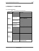
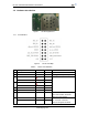
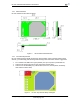
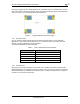
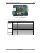
Table Of Contents

HF-A21 Embedded WiFi Module User Manual
Shanghai High-Flying Electronics Technology Co., Ltd
www.hi-flying.com
9
High-Flying suggest HF-A11 module better locate in following region at customer board, which to
reduce the effect to antenna and wireless signal, and better consult High-Flying technical people
when you structure your module placement and PCB layout.
Figure 5. Suggested Module Placement Region
1.2.4. External Antenna
HF-A11 modules support internal antenna and external antenna option for user dedicated
application. If user select external antenna, HF-A11 modules must be connected to the 2.4G
antenna according to IEEE 802.11b/g/n standards.
The antenna parameters required as follows:
Table 3 HF-A11 External Antenna Parameters
1.2.5. Evaluation Kit
High-Flying provides the evaluation kit to promote user to familiar the product and develop the
detailed application. The evaluation kit shown as below, user can connect to HF-A21 module with
the RS-232 UART port, 100M Eth port or Wireless port to configure the parameters, manage the
module or do the some functional tests.
Item Parameters
Frequency range 2.4~2.5GHz
Impedance 50 Ohm
VSWR 2 (Max)
Return Loss -10dB (Max)
Connector Type I-PEX or populate directly