
User's Manual
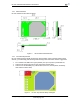
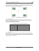
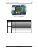
Table Of Contents

HF-A21 Embedded WiFi Module User Manual
Shanghai High-Flying Electronics Technology Co., Ltd
www.hi-flying.com
8
1.2.2. Mechanical Size
HF-A21 modules physical size as follows:
Figure 3. HF-A21 Mechanical Dimension
1.2.3. On-board Chip Antenna
HF-A11 module support internal ob-board chip antenna option. When costomer select internal
antenna, you shall comply with following antenna design rules and module location suggestions:
For customer PCB, RED color region (6x8mm) can’t put componet or paste GND net;
Antenna must away from metal or high components at least 10mm;
Antenna can’t be shieldedby any meal enclosure; All cover, include plastic, shall away
from antenna at least 10mm;
Figure 4. HF-A11 Chip Antenna Keep Out Region