
User's Manual
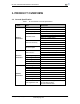
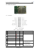
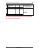
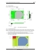
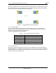
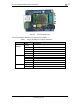
Table Of Contents

HF-A21 Embedded WiFi Module User Manual
Shanghai High-Flying Electronics Technology Co., Ltd
www.hi-flying.com
6
1.2. Hardware Introduction
Figure 1. HF-A21 Appearance
1.2.1. Pins Definition
Figure 2. HF-A21 Pins Map
Table 2 HF-A21 Pins Definition
Pin
Description
Name
Direction
Note
1
Ground
GND
Power
2
VCC
3.3V
Power
3.3V @ 350mA power input
3
UART Data Transmit
UART_TXD
NOTE1
O
GPIO
GPIO12
I/O
4
UART Data Receive
UART_RXD
NOTE2
I
GPIO
GPIO13
I/O
5
GPIO
GPIO4
I/O
6
GPIO
GPIO5
I/O
7
Module reset signal
RESET
I
“Low ( 0 )” effective reset input.
The reset duration should be
kept more than 300ms
8
WiFi status Indication
nLink
O
“1”- WIFI connection available,
“0”- No WIFI connection
Can be configured as GPIO.
GPIO
GPIO0
I/O