
User's Manual
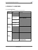
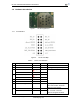
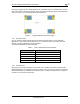
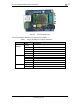
Table Of Contents

HF-A21 Embedded WiFi Module User Manual
Shanghai High-Flying Electronics Technology Co., Ltd
www.hi-flying.com
10
Figure 6. HF-A21 Evaluation Kit
The external interface description for evaluation kit as follows:
Table 4 HF-A21 Evaluation Kit Interface Description
Function
Name Description
External
Interface
DC jack
5~18V power input connector
3-Pin
3-Pin RS485 interface(Reserved)
DB9
Male serial jack of 9-pin,and used to connect to PC
RJ-45 100M Eth Interface
Module 2x7 2mm DIP connector
LED
Power (Red) 3.3V Power Indicator
TXD TXD Indicator
RXD RXD Indicator
Ready nReady/GPIO Indicator
Link nLink/GPIO Indicator
Button
Reset
Used to reset the module.
Reload Module restore to factory default configuration.