
User's Manual


HF-A21-SMT Embedded WiFi Module User Manual
Shanghai High-Flying Electronics Technology Co., Ltd
www.hi-flying.com - 54 -
APPENDIX A: QUESTIONS AND ANSWERS
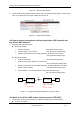
Q1: How to configure transparent serial port application (TCP protocol) with
two HF-A21-SMT modules?
Network structure as below figure:
Module 1# Setting:
Works as AP mode; --See “Mode Selection Page”
LAN IP address: 10.10.100.254; --See “AP Interface Setting Page”
Network Protocal:TCP/Server, Port ID: 8899; -- See “Application Setting Page”
(Module default setting);
Module 2# Setting:
Works as STA mode; --See “Mode Selection Page”
WAN connection type: DHCP or Static IP (For this example:10.10.100.100)
--See “STA Interface Setting Page”
Network Protocal:TCP/Client, Port ID: 8899; Application IP address: Module 1#‟s LAN
IP address (10.10.100.254); -- See “Application Setting Page”
Notes: When module 2# works as STA mode, module‟s WiFi interface works as WAN
port. Module‟s WAN IP address and LAN IP address shall be setting different segment.
So, module 2#‟s LAN IP address must change to other segment; (For this sample, we
change to 10.10.99.254); --See “AP Interface Setting Page”
HF-A21-SMT
AP,
LAN IP:10.10.100.254
TCP, Server
8899
HF-A21-SMT
STA,
LAN IP:10.10.99.254
WAN IP: 10.10.100.100
TCP, Client
10.10.100.254: 8899
1# 2#
WIFI
MCU
MCU
UART
UART
Figure 42. Configure Transparent Serial Port Connection (TCP)
Q2: Where to Set HF-A21-SMT Module LAN IP and WAN IP through Web Page?
HF-A21-SMT Wireless LAN IP address setting see “AP Interface Setting Page” as below Figure,