HF-A11x V3.1 User Manual HF-A11x Embedded WiFi Module User Manual V3.1 Copyright Hi-flying is a registered trademark of Hi-flying Incorporated. Copyright © 2012 Hi-flying Incorporated. All rights reserved. No part of this publication may be reproduced or distributed in any form or by any means, or stored in a database or retrieval system, without the prior written permission of the publisher.
HF-A11x V3.1 User Manual Overview of Characteristic Support IEEE802.
HF-A11x V3.1 User Manual TABLE OF CONTENTS LIST OF FIGURES.................................................................................................................................. 6 LIST OF TABLES ................................................................................................................................... 7 HISTORY................................................................................................................................................. 8 1.
HF-A11x V3.1 User Manual 2.11. GPIO Function ................................................................................................................... 29 3. OPERATION GUIDELINE ......................................................................................................... 30 3.1. Configuration via Web Accessing....................................................................................... 30 3.1.1. Open Web Management Interface ................................................
HF-A11x V3.1 User Manual 4.2.2.25. 4.2.2.26. 4.2.2.27. 4.2.2.28. 4.2.2.29. 4.2.2.30. AT+EPHY ................................................................................................................. 49 AT+RELD ................................................................................................................. 49 AT+Z ......................................................................................................................... 49 AT+MID.......................................
HF-A11x V3.1 User Manual LIST OF FIGURES Figure 1. Figure 2. Figure 3. Figure 4. Figure 5. Figure 6. Figure 7. Figure 8. Figure 9. Figure 10. Figure 11. Figure 12. Figure 13. Figure 14. Figure 15. Figure 16. Figure 17. Figure 18. Figure 19. Figure 20. Figure 21. Figure 22. Figure 23. Figure 24. Figure 25. Figure 26. Figure 27. Figure 28. Figure 29. Figure 30. Figure 31. Figure 32. Figure 33. Figure 34. Figure 35. Figure 36. Figure 37. Figure 38. Figure 39. Figure 40. Figure 41. Figure 42. Figure 43.
HF-A11x V3.1 User Manual Figure 48. Figure 49. Figure 50. Module Network Protocol: UDP ....................................................................................... 53 Two HF-A11x Modules Connection Through AP ............................................................ 54 Wireless Data Acquisition Card Setting........................................................................... 55 LIST OF TABLES Table 1 Table 2 Table 3 Table 4 Table 5 Table 6 HF-A11x Module Technical Specifications.....
HF-A11x V3.1 User Manual HISTORY Ed. V3.1 Created on 1-14-2012. Shanghai High-Flying Electronics Technology Co., Ltd www.hi-flying.
HF-A11x V3.1 User Manual 1. PRODUCT OVERVIEW 1.1. General Specification Table 1 Class Wireless Parameters HF-A11x Module Technical Specifications Item Certification FCC/CE Wireless standard US Frequency range EU Frequency range 802.11 b/g/n 2.412GHz-2.462GHz 2.412GHz-2.472GHz 802.11b: +17.38 dBm (Max.) 802.11g: +14.64 dBm (Max.) 802.11n: +14.95 dBm (Max.) Configurable 802.11b: -89 dBm 802.11g: -81dBm 802.11n: -71dBm Internal:On-board chip antenna UART: 1200bps - 230400bps GPIOs Ethernet: 100Mpbs 3.
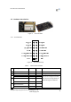
HF-A11x V3.1 User Manual 1.2. Hardware Introduction Figure 1. 1.2.1. HF-A11x Demo Pins Definition Figure 2. Table 2 HF-A11x Pins Map HF-A11x Pins Definition Pin Description Name 1 2 3 Ground VCC UART Data Transmit GPIO UART Data Receive GND 3.3V UART_TXD GPIO3 UART_RX D GPIO4 UART_RTS 4 5 GPIO UART sends request of data transmission GPIO GPIO5 Directio n Power Power O I/O I Note 3.
HF-A11x V3.1 User Manual 6 UART receives data transmission permission GPIO UART_CTS GPIO6 I/O 7 Module reset signal RESET I 8 WiFi status Indication GPIO nLink GPIO8 O I/O 9 Indicate the module status of power on process GPIO Restore configuration GPIO nReady O GPIO9 nReload GPIO10 I/O I I/O 11 Ethernet Interface PHY_RX+ I 12 13 14 Ethernet Interface Ethernet Interface Ethernet Interface PHY_RXPHY_TX+ PHY_TX- I O O 10 I Shanghai High-Flying Electronics Technology Co., Ltd www.
HF-A11x V3.1 User Manual 1.2.2. Mechanical Size HF-A11x series modules include HF-A111(25×40mm)and HF-A112(30×45mm)with different physical size as follows: Figure 3. HF-A111 Mechanical Dimension Shanghai High-Flying Electronics Technology Co., Ltd www.hi-flying.
HF-A11x V3.1 User Manual Figure 4. HF-A112 Mechanical Dimension 1.2.3. Evaluation Kit High-Flying provides the evaluation kit to promote user to familiar the product and develop the detailed application. The evaluation kit shown as below, user can connect to HF-A11x module with the RS-232 UART port, 100M Eth port or Wireless port to configure the parameters, manage the module or do the some functional tests. Figure 5.
HF-A11x V3.1 User Manual Table 3 Function External Interface LED Button Name HF-A11x Evaluation Kit Interface Description Description Male serial jack of 9-pin,and used to connect to PC DB9 RJ-45 Mini USB Module Power (Red) CTS RTS Reload Ready Link Reset Reload 100M Eth Interface B-type interface, work as 5V@1A input 2x7 2mm DIP connector 3.3V Power Indicator CTS/GPIO Indicator RTS/GPIO Indicator nReload/GPIO Indicator nReady/GPIO Indicator nLink/GPIO Indicator Used to reset the module.
HF-A11x V3.1 User Manual 1.3. Hardware Reference Design 1.3.1. Hardware Typical Application Figure 7. HF-A11x Hardware Typical Application Notes: nRST- Module hardware reset signal. Input. Logics “0” effective. There is 100K Ohm pull-up resister internal. When module power up or some issue happened, MCU need assert nRST signal “0” at least 300ms, then set” 1” to keep module fully reset. nReady- Module boot up ready signal. Output. Logics “0” effective. There is 4.7K Ohm pull-up resister internal.
HF-A11x V3.1 User Manual 1.3.2. 10/100M Ethernet Interface HF-A11x modules provide one 10/100M Ethernet PHY layer interface for data transition or user configuration. This Ethernet support with transformer and without transformer (PHY-to-PHY) 2 kinds of connection. 1.3.2.1. Ethernet Connection with Transformer User board put Ethernet transformer and RJ-45 connector. This is a general 10/100M Ethernet phy layer connection. The reference design as following: Figure 8.
HF-A11x V3.1 User Manual User can add RS-232 chipset on user board and convert the signal to RS-232 voltage to communicate with outside equipment or sensors. HF-A11x modules UART interface include 4 general signals: TXD/RXD/RTS/CTS. The hardware reference design with RS-232 chipset as following: Figure 10. UART Interface Reference Design Notes: TXD pin is also hardware configuration pin internal module. So this pin MUST pull-down during module power up.
HF-A11x V3.1 User Manual 1.4. Software Reference Design When HF-A11x modules boot up phase, the general user board MCU software flow chart will as following: Figure 11. User MCU Software Flow Chart HF-A11x modules provide two kinds of work mode and one configuration mode. Work mode is Transparent Transmission and Agreement Transmission. Configuration mode is through AT+instruction set to finish module setting and configuration.
HF-A11x V3.1 User Manual High-Flying recommend when doing large amounts of data transmitting in transparent transmission mode, hardware flow control should be enabled, so as to fully ensure reliable data transmission. In the applications which doesn’t need flow control, users can simply leave RTS / CTS pin vacant. 1.4.2.
HF-A11x V3.
HF-A11x V3.1 User Manual Figure 12. User Device Send Data to HF-A11x Module Procedure Notes: For Error scheme 1, if HF-A11x receives wrong CRC information of “SEND” command, it will reply back “SEND ACK”=NOK. If HF-A11x not receives “SEND” command for the link issue, user device need decide to retry. (This is a procedure HF-A11x module send data to user device procedure) Figure 13. HF-A11x Module Send Data to User Device Procedure 1.4.2.3.
HF-A11x V3.1 User Manual { u32 cksum=0; u16 *p=data; while (len > 1) { cksum += *p++; len -=2; } if (len) { cksum += *(u8 *)p; } cksum = (cksum >> 16) + (cksum & 0xffff); cksum += (cksum >>16); return ~cksum; } --------------------------------------------1.4.3. Configuration Mode In configuration mode, user can finish HF-A11x module configuration management and parameters setting work.
HF-A11x V3.1 User Manual 1.4.5. Palmodic Signal Base on selected factory default setting, nReady signal can have two output statuses: ¾ Status One: The module will output “0” after normal boot up. This signal used to judge if module finish boot up and ready for application. ¾ Status Two: The module will output “Palmodic Signal” after normal boot up.The palmodic signal is 0.5Hz square wave with dutyfactor 1:1. User can query this signal to judge if moduleis active “live” or need to re-boot.
HF-A11x V3.1 User Manual 2. FUNCTIONAL DESCRIPTION 2.1. Wireless Networking HF-A11x module can be configured as both wireless STA and AP base on network type. Logically there are two interfaces in HF-A11x. One is for STA, and another is for AP. When HFA11x works as AP, other STA equipments are able to connect to wireless LAN via HF-A11x module. Wireless Networking with HF-A11x is very flexible. Following figure shows the functional architecture of HF-A11x module: Figure 15.
HF-A11x V3.1 User Manual AP, this type of network is a loose structure, all the STAs in the network can communicate directly. As showing in the figure below, HF-A11x (1) can be treat as an AP, and HF-A11x (2), HF-A11x (3) and the laptop are STAs connected to HF-A11x (1). Meanwhile, all HF-A11x modules can connected to user device via UART interface. All HF-A11x modules can be operated and managed through the laptop. So it is convenient to O&M all HF-A11x modules.
HF-A11x V3.1 User Manual Figure 18. Multi-SSID with STA Notes: This function is user selected factory setting and RELD instruction will not effective for this function. If user not requires this function, the default factory setting is support one SSID when works at STA mode. Contact with Hi-flying for more detailed support. 2.4. UART Auto-Frame HF-A11x support UART auto-frame function.
HF-A11x V3.1 User Manual customer detailed requirement). So, please contact with High-Flying technical support interface to know more about Ethernet interface networking application. 2.6.1. HF-A11x Ethernet Interface Networking (As AP) Figure 19. HF-A11x Ethernet Interface Networking (As AP) For above networking, HF-A11x module works as AP and also the centre of this network.
HF-A11x V3.1 User Manual For above networking, HF-A11x module works as STA(Firmware is Z-Version),and module configured as bridge mode. When module connect to AP, all devices connected to module Ethernet interface will get assigned IP address from AP (For example: 192.168.1.101).For module works as bridge mode, it can be treated as a transparent device and PC1, PC2 can communicate without any limit. But in this networking, HF-A11x module needs assign a static LAN IP address (For example: 192.168.1.
HF-A11x V3.1 User Manual Figure 22. HF-A11x Transparent Transmission Demo 2.8. Network Protocol HF-A11x module supports TCP/UDP network protocol and the port parameters can be set via web accessing or AT+instruction set. 2.9. Parameters Configuration HF-A11x module supports two methods to configuration parameters: Web Accessing and AT+instruction set. Web accessing means users can configure parameters through Web browser.
HF-A11x V3.1 User Manual 3. OPERATION GUIDELINE 3.1. Configuration via Web Accessing When first use HF-A11x modules, user may need some configuration. User can connect to HFA11x module’s wireless interface with following default setting information and configure the module through laptop. Table 4 HF-A11x Web Access Default Setting Parameters SSID Default Setting HF-A11x_AP IP Address 10.10.100.254 Subnet Mask 255.255.255.0 User Name admin Password admin 3.1.1.
HF-A11x V3.1 User Manual Figure 24. Mode Selection Page 3.1.3. AP Interface Setting Page This page use to setting the parameters when HF-A11x module works as AP. Figure 25. AP Interface Setting Page 3.1.4. STA Interface Setting Page This page use to setting the parameters when HF-A11x module works as STA. Such as SSID of AP which module need to connected, and also select the networking type: DHCP or static IP address. Shanghai High-Flying Electronics Technology Co., Ltd www.hi-flying.
HF-A11x V3.1 User Manual Figure 26. STA Interface Setting Page 3.1.5. Application Setting Page This page use to setting the parameters of serial port communication, such as UART setting and high layer network protocol setting which used support serial communication. Figure 27. Application Setting Page Shanghai High-Flying Electronics Technology Co., Ltd www.hi-flying.
HF-A11x V3.1 User Manual Notes: Generally, Network protocols support three modes: TCP Server, TCP Client, and UDP. UDP has no server and client requirement according to standard. Besides module working as TCP Server (IP address not required in this mode). User must set the IP address of the device which need communicate with HF-A11x module. Also the Port ID between two sides of the communication devices must keep the same. 3.1.6.
HF-A11x V3.1 User Manual 3.2.2. Network Connection User can select two methods to connect HF-A11x module base on dedicated application. ¾ Use HF-A11x STA interface HF-A11x and debug PC2 connect to a wireless AP, another PC1 (or user device) connect to HFA11x module with serial port: Figure 29. STA Interface Debug Connection ¾ Use HF-A11x AP interface Debug PC2 connect to HF-A11x through wireless connection, another PC1 (or user device) connect to HF-A11x module with serial port. Figure 30.
HF-A11x V3.1 User Manual PC2 open “TCPUDPDbg” program, and create a new connection. If HF-A11x configured as Server mode, “TCPUDPDbg” Tools shall create “Client “mode connection. Or otherwise, create a “Server” mode connection. Figure 32. “TCPUDPDbg” Tools Create Connection Then setting the TCP/UDP connection parameters. Default as following: Figure 33. “TCPUDPDbg” Tools Setting Then, click “Create” button to create a connection. Shanghai High-Flying Electronics Technology Co., Ltd www.hi-flying.
HF-A11x V3.1 User Manual Figure 34. “TCPUDPDbg” Tools Connection Now, in transparent transmission mode (HF-A11x default setting), data can be transferred from “CommTools” program to “TCPUDPDbg” program, or in reverse. You can see data in receiver side will keep same as in sender side. 3.3. Typical Application Examples 3.3.1. Wireless Control Application Figure 35. Wireless Control Application For this wireless control application, HF-A11x works as AP mode. Module’s serial port connects to user device.
HF-A11x V3.1 User Manual 3.3.2. Remote Management Application Figure 36. Remote Management Application For this remote management application, HF-A11x works as STA mode and connects to Internet through wireless AP. Module configured as TCP Client and communicates with remote TCP server at Internet. Module’s serial port connects to user device. So, user device’s data or sampling information can send to remote TCP server for storage or processing.
HF-A11x V3.1 User Manual module through serial port can communicate each other and think the connection between them is fully transparent. 3.3.4. Wireless Data Acquisition Card Application For this wireless data acquisition card application, one PC works as data server and every data acquisition card connects with a HF-A11x module to support wireless connection function. Figure 38.
HF-A11x V3.1 User Manual 4. AT+INSTRUCTION INTRODUCTION 4.1. Configuration Mode When HF-A11x power up, it will default works as transparent transmission mode, then user can switch to configuration mode by serial port command. HF-A11x UART default parameters setting as below figure, Figure 39. HF-A11x Default UART Port Parameters In configuration mode, user can setting the module through AT+ instruction set, which cover all web page setting function. 4.1.1.
HF-A11x V3.1 User Manual 4.2. AT+ Instruction Set Overview User can input AT+ Instruction through hyper terminal or other serial debug terminal, also can program the AT+ Instruction to script. User can also input “AT+H” to list all AT+ Instruction and description to start. Figure 41. ”AT+H” Instruction for Help 4.2.1. Instruction Syntax Format AT+Instruction protocol is based on the instruction of ASCII command style, the description of syntax format as follow.
HF-A11x V3.1 User Manual ¾ RSP: Response string; “ok” : Success “ERR”: Failure [op] : = [para-n]: Parameters if query command or Error code when error happened; : ASCII 0x0d; : ASCIII 0x0a; Error Code Table 5 4.2.2.
HF-A11x V3.1 User Manual MAXSK EPHY RELD Z MID VER H Set/Query maxima TCP connection Open/Close ETH interface Restore to factory default setting Re-start module Query module ID information Query module software version information Help Notes: HF-A11x module can works as AP or STA, user have to use different AT+ Instruction to set WiFi parameters when module works as AP or STA mode. 4.2.2.1.
HF-A11x V3.1 User Manual 4.2.2.4.
HF-A11x V3.1 User Manual Query Operation AT+ UARTFL +ok=< LF >< LF > Set Operation AT+ UARTFL= +ok< LF >< LF > Parameters: len: Range 64 ~4096; Unit: byte. Auto-frame trigger length; 4.2.2.8.
HF-A11x V3.1 User Manual NONE: When “auth=OPEN”, effective WEP: When “auth=OPEN” or “SHARED”, effective TKIP: When ”auth= WPAPSK”, effective AES: When “auth= WPAPSK”, effective key: password, ASCII code, shall less than 64 bit and greater than 8bit This Instruction only effective for HF-A11x works as STA. After HF-A11x module boots up again, the setting will be effective. But user can set this command when module configured as AP. 4.2.2.11.
HF-A11x V3.1 User Manual AT+WEBU +ok=< LF >< LF > Set Operation AT+ WEBU=< usr,password > +ok< LF >< LF > Parameters: usr: User name for WEB page access; password:Password for WEB page access; 4.2.2.15.
HF-A11x V3.1 User Manual This Instruction only effective for HF-A11x works as AP. After HF-A11x module boots up again, the setting will be effective. But user can set this command when module configured as STA. 4.2.2.17. AT+MSLP Function: Set modules into power save mode.(Turn OFF WiFi); Format: Query Operation AT+ MSLP +ok=
HF-A11x V3.1 User Manual mask: WAN port subnet mask; gateway: WAN port gateway address; This Instruction only effective for HF-A11x works as STA. After HF-A11x module boots up again, the setting will be effective. But user can set this command when module configured as AP. 4.2.2.21.
HF-A11x V3.1 User Manual AT+ MAXSK = +ok< LF >< LF > Parameters: num: 1~32, default 32. maxima TCP connection; When configure as TCP/Server, HF-a11x support maxime 32 TCP connections. If not require so much connection, user can resetting this parameters. 4.2.2.25.
HF-A11x V3.1 User Manual Query Operation AT+H +ok=< LF >< LF > Parameters: commod help: command introduction; Shanghai High-Flying Electronics Technology Co., Ltd www.hi-flying.
HF-A11x V3.1 User Manual APPENDIX A: QUESTIONS AND ANSWERS Q1: How to configure transparent serial port application (TCP protocol) with two HF-A11x modules? ¾ Network structure as below figure: Module 1# Setting: Works as AP mode; --See “Mode Selection Page” LAN IP address: 10.10.100.
HF-A11x V3.1 User Manual Figure 44. Module WAN IP Setting Q3: How to configure transparent serial port application (UDP protocol) with two HF-A11x modules? ¾ Network structure as below figure: Module 1# Setting: Works as AP mode; --See “Mode Selection Page” LAN IP address: 10.10.100.254; --See “AP Interface Setting Page” Network Protocal:UDP, Port ID: 8899; Application IP address:10.10.100.
HF-A11x V3.1 User Manual Figure 46. Module Network Protocols: TCP/Server Protocol: TCP Client Application IP address required: it’s target TCP server ‘s IP address; Port ID required: 8899 (Default) Figure 47. Module Network Protocol: TCP/Client Protocol: UDP No Server/Client selection required; Application IP address required: it’s target device ‘s IP address; Port ID required: 8899 (Default) Figure 48.
HF-A11x V3.1 User Manual Network Protocal:TCP/Server, Port ID: 8899; -- See “Application Setting Page” LAN IP address: 10.10.99.254 (Different net segment with WAN port); --See “AP Interface Setting Page” Module 3# Setting: Works as STA mode; --See “Mode Selection Page” WAN connection type: Static IP: 10.10.100.101; --See “STA Interface Setting Page” Network Protocal:TCP/Client, Port ID: 8899; Application IP address: Module 2#’s WAN IP address (10.10.100.
HF-A11x V3.1 User Manual Network Protocal:TCP/Client, Port ID: 8899; Application IP address:10.10.100.100; Module 2# Setting: Works as STA mode; WAN connection type: Static IP: 10.10.100.101; Network Protocal:TCP/Client, Port ID: 8899; Application IP address:10.10.100.100; LAN IP address: 10.10.99.254 (Different net segment with WAN port); Module 3# Setting: Works as STA mode; WAN connection type: Static IP: 10.10.100.
HF-A11x V3.
HF-A11x V3.1 User Manual else do nothing; function do_recv_ack_cmd() if (receiv RECV ACK and check OK & is_waiting_for_recv_ack) { agree_data.recv_s++; agree_data.
HF-A11x V3.1 User Manual APPENDIX C: CONTACT INFORMATION ------------------------------------------------------------------------------------Address: No.456, B101, BiBo Road, PuDong, Shanghai, China, 201203 Web: www.hi-flying.com Tel: 0086-21-33908861-8017, 0086-13916319365 Mail: sales@hi-flying.com, senxie@hi-flying.com ------------------------------------------------------------------------------------- Shanghai High-Flying Electronics Technology Co., Ltd www.hi-flying.
HF-A11x V3.1 User Manual FCC RF EXPOSURE REQUIREMENTS 1 STANDARDS AND REGULATORY COMPLIANCE 1.1 Standards and certification The EUT conforms to the following standards and certification requirements: 802.11 b/g/n FCC ❒ 47 CFR Part 1 - RF radiation exposure limits ❒ 47 CFR Part 2 - Equipment authorization ❒ 47 CFR Part C - WIFI 1.2 FCC certification requirements. According to the definition of mobile and fixed device is described in Part 2.1091(b), this device is a mobile device.
HF-A11x V3.1 User Manual ❒ 802.11g band <0.8 dBi ❒ 802.11n band <0.8 dBi 5. This module must not transmit simultaneously with any other antenna or transmitter 6. The host end product must include a user manual that clearly defines operating requirements and conditions that must be observed to ensure compliance with current FCC RF exposure guidelines. For portable devices, in addition to the conditions 3 through 6 described above, a separate approval is required to satisfy the SAR requirements of FCC Part 2.
HF-A11x V3.1 User Manual The user manual or instruction manual for an intentional or unintentional radiator shall caution the user that changes or modifications not expressly approved by the party responsible for compliance could void the user's authority to operate the equipment.
HF-A11x V3.1 User Manual 1.4 National Restrictions END OF DOCUMENT © Copyright High-Flying, May, 2011 The information disclosed herein is proprietary to High-Flying and is not to be used by or disclosed to unauthorized persons without the written consent of High-Flying. The recipient of this document shall respect the security status of the information. The master of this document is stored on an electronic database and is “write-protected” and may be altered only by authorized persons at High-Flying.