User Manual 2217 West Braker Lane Austin, TX 78758 USA (512) 836-2242 www.highend.
Power Cue DMX TM © 1999 High End Systems, Inc. Power Line 2217 West Braker Lane Austin, TX 78758 USA www.highend.com (512) 836-2242 QCOMM/ENG/2.
CONTENTS I. Introduction II. SetUp General Principles Front Panel Layout and Function Rear Panel Layout and Function Passcodes Channel Names Keys - Latch, Flash, Swap, Solo Fixtures - Selecting Types, Setting DMX Address Groups Channel Types - HTP, LTP, Permanent - Dim, Switch, Snap Patch - The Input Extender Comms. - RS232, MIDI 1 2 4 6 8 10 12 14 16 20 22 III.
© High End Systems, Inc. 1999, All Rights Reserved Information and specifications in this document are subject to change without notice. High End Systems, Inc. assumes no responsibility or liability for any errors or inaccuracies that may appear in this manual. The system software for Power Cue DMX described in this manual is furnished under license, and is protected by copyright law and international treaties.
Product Modification Warning High End Systems products are designed and manufactured to meet the requirements of United States and International safety regulations. Modifications to the product could affect safety and render the product non-compliant to relevant safety standards. Mise En Garde Contre La Modification Du Produit Les produits High End Systems sont conçus et fabriqués conformément aux exigences des règlements internationaux de sécurité.
GENERAL PRINCIPLES The Power Cue DMX is designed to control most types of intelligent and generic lighting that will be encountered in entertainment venues today. It has the following capacities: •256 DMX output channels •512 scenes •64 chases of 64 steps •16 groups •16 intelligent fixtures •29 channels (max.
looks. It may be programmed in real time by storing actual events as they happen. You may subsequently edit the list of events and their desired run times. Memory Card The Power Cue DMX has a PCMCIA memory card slot which allows you to save all your programming to a suitable memory card. Conversely you may upload from a memory card into the Power Cue DMX. New versions of the operating system may be loaded via a memory card and new intelligent fixture personalities may also be uploaded via the card slot.
may be driven by the Power Cue DMX. They may also be programmed to contain pre-defined groups of channels and subsequently during scene programming to call these groups into a scene. They may also be used as output keys. In RUN mode (playback) they are used to recall those effects programmed into them. In this context they may be set to latch, flash, swap or solo. Touchkeys There are sixteen illuminated touchkeys. These may be set to latch, flash, swap or solo.
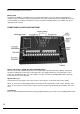
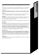
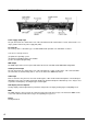
REAR PANEL LAYOUT AND FUNCTIONS Power supply (PSU) input The pin connections are shown on the rear of the unit and later in this manual in the section, “Connections”. Use only a genuine Power Line power supply unit (PSU). PC Card slot The memory card is a PC Card Type 1, 512Kb SRAM. Card operations are dealt with in section V.
5
Before you can use the Power Cue DMX there are several features that should be configured via the set up menu. When you switch on the Power Cue DMX, the first screen you see will show several options, one of which is SetUp. At other times SetUp may be accessed by pressing Escape when the display shows RUN MODE. SET UP PASSCODES You may set passcodes to protect the Prog/Edit menu, the Setup menu and the Card menu. The code to the setup menu is the master and has global access.
!!! All the instruction sequences in this manual start from the MAIN MENU screen. If you are in RUN mode, press ESCAPE to get to MAIN MENU. 4. Now you can proceed to the SetUp menu and select the passcode option. 3. Use the numeric keypad to enter the current 4-digit code. Press YES. •Press Setup •Enter current code •Press Pswd •Select menu to protect •Enter current code •Enter new code 7. Enter the NEW passcode, using the numeric keypad, like you did in step 3 and press STORE.
SET UP CHANNEL NAMES This section discusses how to name channels, which can make them easier to remember. 1. Press SetUp. Enter the SetUp passcode, if 2. Press ChnName active. 4. Enter or edit the channel name as shown in step 5. NOTE: Channels used by fixtures are named automatically during the setup fixtures routine. The automaticallyassigned names may not be overwritten. If you are using fixtures, install them first. 8 5.Use the alpha-numeric pad to enter a new name or edit the existing one.
3. Scroll through the channels list, using the UP and DOWN buttons. Press STORE to select a channel.
SET UP KEYS Both the push buttons and the touchkeys may be configured according to the following options. Both the buttons and the keys are grouped left and right over two pages. A selected attribute applies to all keys in the group. 1. Press SetUp. Enter the passcode, if prompted.
3. Select a group of keys to setup. Scroll through the options to make your selection. Repeat this procedure for other groups. Press STORE and return to step 2. •Press SetUp •Press Keys •Select a group of keys •Bump to the desired option •Press STORE when finished These are the available functional modes. Except where the function is Global, it applies only within the group:Latch and Add - A pressed key remains switched on until pressed a second time. All keys may be switched on at any one time.
SET UP FIXTURES The Power Cue DMX contains a library of a great number of intelligent fixture personalities. Before you can use a fixture, it must first be assigned a personality and a DMX start address. 1. Press SetUp. Enter the passcode, if prompted. 12 2. Press Fixts. The Power Cue DMX can control up to 16 fixtures. They will appear in the display as nos. 01-16 and initially have no personality, i.e. they are UNASSIGNED. You will next select a personality for each fixture you wish to control. 4.
3. Scroll to the fixture number you want to set up and press ASSIGN. If you attempt to assign a fixture that is already assigned, you may adjust the PAN, TILT and AXIS but not the DMX address. To change the DMX address, you must first remove the fixture and then re-assign it with the new address. When setting up your fixtures you will need to make certain DIP switch selections on the fixture itself. Often there are two DIP switches, one for the personality and one for the DMX start address setting.
SET UP GROUPS Where you need to use certain channels together on a regular basis, you will find it easier and quicker to call them into a scene as one group, rather than many individual channels. This routine shows you how to define the channels in a group. You may define a total of 16 groups. 1. Press SetUp. Enter the SetUp passcode, if 2. Press Group. prompted. 4. Press one of the sixteen illuminated push 5. Scroll through the channels and buttons. This is where the groups will reside.
3. Select the group to setup. NOTE: Setting up one of the 16 groups for a second time will result in the original setup being overwritten.
SET UP CHANNEL TYPES Just as each channel may be named, it may also be given certain characteristics to determine how it will respond to a control signal: •what function is assigned to it. •whether the channel may be faded, switched or snapped. •whether it works HTP, LTP or is permanently on. •whether it responds to the DBO switch, the Master fader, both or neither. When the Power Cue DMX is first switched on, all channels are set by default to type = dimmer/DBO, mode = fade and output = HTP.
•OUTPUT Outputs are either LTP, HTP or PERM. A channel can only output one level at any one time. If it receives more than one output command, which one should it choose to obey? LTP, HTP and PERM lays down the rules for this situation, following conventions established for various types of device. LTP channels respond to the latest command received. Most intelligent light channels are customarily set to LTP, allowing, for example, overlayed color/gobo information, hence last takes precedence, or LTP.
SET UP CHANNEL TYPE 1. Press SetUp. Enter the setup menu passcode, if prompted. 18 2. Press ChnTyp.
•Press SetUp •Press ChnTyp •Set the attributes •Press STORE 3. Scroll to the desired channel and adjust the attributes. Then press ESCAPE. See the notes opposite for an explanation of the attributes.
SET UP PATCH - THE FADER PANEL The Power Cue DMX allows you to patch various types of effect to an external control device, usually with faders, so that such effects may be faded in and out or set at varying levels and not just switched on and off. The Power Cue DMX lets you make 16 of these patches. Power Line produces the Power Cue DMX Fader Panel specifically for this purpose. Your Power Cue DMX may have been delivered complete with a Fader Panel already fitted.
1. Press SetUP 2. Press Patch. • Press SetUp • Press Patch • Choose Type, Item and Method • Press STORE 3. Scroll to one of the 16 available patches. Select the effect TYPE you want to use (scene, chase, et.c.) and then use the trackball to scroll through the scene list (chase list et.c.). to select the item to patch. Use the METHOD button to select a patch of all channels within the effect or just the HTP channels. Press STORE when finished.
SET UP COMMS. The Power Cue DMX may be set up to communicate using MIDI or RS232, depending on the functionality required. Jumpers on the Power Cue DMX's main circuit board may need to be set to change from the factory setting of MIDI to RS232. This procedure is illustrated in the boxes on the right. See the options section and MIDI Appendix for further information. RS232 functions not yet implemented. 1. Press SetUp. 22 2. Press Comms.
Position jumpers as shown to set the Comms. mode for either MIDI or RS232. •Press SetUp •Press Comms •Press STORE •Press ESCAPE 3. Press STORE to initialise the Comms mode. 4. Check display to verify that the desired Comm mode has been initialised. Press ESCAPE to return to main menu.
PROGRAMMING SCENES - AN OVERVIEW All output is made from the push buttons and the touchkeys. The object of programming is to create effects and then to load those effects on to the push buttons and the touchkeys for output. The basic building unit is the channel. Channels may be loaded directly on to output keys or they may be combined into scenes. All 256 channels are freely programmable and none are dedicated to any specific function.
previously-defined group. The scene is then further defined by giving it certain attributes to determine its appearance: •It may appear as a static scene. In this case you have the option to set fade in and fade out times. Besides driving generic lighting a static scene could be used to energise strobes or smoke machines or to operate motors. •It may appear as a sound-to-light-scene and each channel may be set to respond to bass, tenor, alto or treble input. •It may appear as a zone (chasing channels).
PROGRAMMING A SCENE WITH MOVING LIGHTS - CONTINUED 5. Select the fixtures to include in the scene, using the illuminated push buttons. During setup you allocated personalities and DMX addresses to fixtures 1-16. Fixtures 1-16 were automatically assigned to the 16 illuminated push buttons above the touchkeys. These buttons are now flashing. Push one or more buttons to select fixtures. If more than one fixture is selected, they must be of the same type. 6.
The display shows the type of fixture being used, the attribute currently being adjusted and the level of the channel (or two channels in the case of XYmirror movement), expressed as a number between 0 and 255 (or 0 and 65535 in the case of 16-bit mirror channels). You may now want to retain the adjustments made so far and make changes to other fixtures. 7. Press STORE to save the scene or ESCAPE to abort the programming.
PROGRAMMING A SCENE WITH MOVING LIGHTS - CONTINUED 8. Give the scene a name. Use the alphanumeric keypad to name or re-name a scene, using the yellow legend. One press of the button marked ABC will display an A above the cursor ^. A second press will display a B, a third press will display a C and a fourth press a 1. Move the cursor one space right by pressing NextChar and one space left by pressing PrevChar or if you pause between presses, the cursor automatically advances to the next character.
9. The scene was saved in step 7. Press ESCAPE now to go back to step 3. and exit to the main menu. Press STORE to go to step 4. and start programming a scene in the next scene memory. •Name the scene •Press ESC to exit, STORE to program another scene Where there are several sequential scenes with the same name, the Power Cue DMX will give them a number in addition to the name.
SAVEPALET EXPLAINED SavePalet is used with moving light scene programming to enable you to repeat settings of the various attributes during later programming. You may save 16 settings of each fixture attribute. Remember that it works with any individual attribute, not whole scenes; whole scenes may be repeated using COPY. Here is an example of how you might use SavePalet to facilitate your color programming.
What Is TRANSPARENCY? How Does OVERLAY work? Overlay allows you to generate scenes where only the channels you choose to use are included in the scene. All other channels remain transparent. While an attribute is selected, press OVERLAY, and the corresponding channels become overlay channels. Press OVERLAY again to turn off the feature. OVERLAY will be shown in the display next to the channel level indication. The words OVERLAY ENABLED will show in the display if any attributes have been tagged OVERLAY.
PROGRAMMING SCENES USING PRESET FOCUS Preset focuses or position memories allow you to speed up the programming of fixtures into scenes by linking channels to a library of scenes that you have previously programmed for this purpose. In the Power Cue DMX this library can contain 46 scenes of the 512 available, i.e. nos. 450-495 and in the scene list these scenes are indicated with a 'p' on the right hand side of the display.
subsequent selection. An attempt to make a second link will produce the message in the display ‘No linkable channels’. Links cannot apply to transparent channels. If you adjust a linked channel in the client scene, the link for that channel is broken and the link to the preset is broken completely if all linked channels are manually adjusted. Channels (in client scenes) which have been manually adjusted must be made transparent before they can be linked again.
AUTO CHECK When you set Auto Check to on, as described in the system options section later in this manual, the Power Cue DMX automatically checks for programming errors and corrupt data held in memories. 1. When you are programming, if you see the arrowed message, press STORE to track down the error. The display changes according to the button that you press. In this example there is an error in chase programming. 2. Press each of the buttons in turn to identify in which type of program the error occurs.
16 BIT MIRROR FADES Where the fixture(s) you are programming support 16-bit mirror fades, the Power Cue DMX automatically makes this feature available, giving you 65536 steps of adjustment instead of 256. MIRROR LOCKS One press of the Mirror button on the alphanumeric keypad will show XY mirror in the display and allow you to adjust both mirror axes. A second press will display X mirror and allow adjustment of the X axis only. A third press will enable XY again and a fourth Y only.
(B) PROGRAMMING CHANNELS INTO A SCENE - GENERIC LIGHTING 2. Press Scene 1. Press Prog/Edit 4. Press Chans to select channels for the scene. Alternatively you may press Group to select any previously-defined group(s) into the scene. See page 30. 5. Scroll through the channel list. All channels not previously programmed are transparent (see page 31 for explanation) until you give them a level by means of the trackball. Press STORE when finished.
3. Scroll up/down the list to find the scene you want. A previously programmed scene will have a name. You may overwrite or edit such scenes. Where there are several scenes with the same name, the Power Cue DMX will automatically give them a number in addition to the name. For example, if two scenes are programmed with the name red wash, the first one is referred to as red wash and the second one as red wash [001]. The COPY and CLEAR options in this screen will be dealt with at the end of this section.
(B) PROGRAMMING GROUPS INTO A SCENE - GENERIC LIGHTING 1. Press Prog/Edit 5. Use the push buttons to select the groups you wish to import into the scene. Push a button a second time to de-select a selected group. 38 2. Press Scene 6. Groups are imported with all channels at brightness level 255. Adjust the level of the group with the trackball. Press STORE when finished adding groups. You can add groups into a scene built from individual channels.
3.Scroll to the desired scene and press STORE. If you are editing a previouslyprogrammed scene, you may enter the scene number on the alphanumeric keypad, instead of scrolling through the scene list. Enter all three digits, e.g. 009, not just 9. 4. Press Group. A previously-programmed scene will have a name. You may overwrite or edit such scenes. Where there are several scenes with the same name, the Power Cue DMX will give them a number in additional to the name.
SELECTING SCENE ATTRIBUTES - GENERIC LIGHTING 1. Press Prog/Edit. 5(a). Scroll through the options under the Type button. If you select MOVING ZONE, this screen appears and you can then adjust the various attributes. When step is not audio, speed is enabled and may be adjusted using the trackball. Slope is either switch or crossfade. Loop is either loop or one-shot. When you push dim the level may be adjusted using the trackball. Bump through the various patterns to choose the zone effect you want.
3. Scroll to the scene to Prog/Edit and press STORE. 4. Press Attrib. •Press Prog/Edit •Press Scene •Select a memory •Press Attrib •Select Type and attributes •Press STORE 6. Save and name the scene. OR 5(c). Bump through the options under the Type button. If you select STATIC SCENE, this screen appears. You may choose to select FadeIn and/or FadeOut times or not. Fade out is disabled by default; it can be enabled via the system options utility.
COPYING AND CLEARING SCENE MEMORIES Existing scenes may be copied from one location to another from within the scene programming menu. Proceed as follows to copy a scene to another memory number. 1. Press Prog/Edit 4(a). Scroll to the scene to copy and press STORE. 2. Press Scene 5(a). Scroll to the new location for the copied scene and press STORE. You have now looped back to step 3. You may continue programming or exit.
3(a). Press COPY •Press Prog/Edit •Press Scene •Press Copy •Select the scene to copy •Select the new scene memory and press STORE To clear a scene memory (delete a scene) repeat steps 1. & 2. above, then do the following:- 3(b). Scroll to the scene you wish to delete and press Clear. 4(b). Confirm that you wish to delete the scene by pressing STORE. You have now looped back to step 3. You may continue programming or exit.
PROGRAMMING A CHASE Scenes made with moving lights may be programmed together into a sequence called a chase. You can also make a chase with scenes of generic lighting. 1. Press Program/Edit 2. Press Chase You may adjust FADE and HOLD for each step or you may choose to have all FADEs of one length and all HOLDs of one length. In this case select GLOBAL. The global time is set later after all the chase steps have been selected.
3. Scroll through the list and select a chase to program by pressing STORE. A previously programmed chase will have a name. You may overwrite or edit such chases. 4. Scroll through the scene list to find the scene you want for this chase step. Press STORE. •Press Prog/Edit •Press Chase •Select a chase memory •Select a scene for each step.
SCENES, CHASES, CHANNELS AND LOOKS ARE LOADED ON TO PUSH- 1. Press Prog/Edit EITHER 4(a) If the key has nothing previously assigned to it, you see this screen. Choose an effect to assign to the key. Then press STORE. 46 2.
BUTTONS OR TOUCHKEYS FOR PLAYBACK 3. Press the pushbutton or touchpad you wish to program. The selected key flashes. Remember that you have available two pages of buttons and two pages of touchkeys. Select the page using the buttons on the left. If the key is in use, you will get the message KEY STILL ACTIVE. You must ESCAPE and switch off the key before you re-program it. PRIORITY RULES FOR PLAYBACK You may assign multiple effects to one output key in combinations of scenes, chases and channels.
SCENES, CHASES, CHANNELS AND LOOKS ARE LOADED ON TO PUSH- 5(a). Scroll through the scene list and press SELECT to include in the keylist a zone, a sound-to-light scene or a static scene with no fade times. Press XREF to include a static scene with its associated fade times. 5(b). Scroll through the chase list and press SELECT to include a chase in the keylist. A selected chased is denoted by a * next to it. Press STORE when finished to go back to step 4.
BUTTONS OR TOUCHKEYS FOR PLAYBACK - CONTINUED 5(c). Scroll to any channel. A channel is transparent until you move the trackball. It is then selected at the level shown. Select one or several channels. Press STORE when finished to go back to step 4. 5(d). Scroll through the look list and press SELECT to include a Look in the keylist. A selected look is denoted by a * next to it. Press STORE when finished to go back to step 4.
REAL TIME SHOW PROGRAMMING A show is a combination of events - scenes, chases, channels and looks. Events may be switched in and out of a show and this makes it different from a look which is a single snapshot of the outputs. The Power Cue DMX allows you to program a show in real time, so that while you play back a series of events, the Power Cue DMX memorises the events, the order in which they are played and their duration. 1. Press Prog/Edit 2. Press Show Adjust Spots Live PROGRAMMING SHOW NO.
Choose SHOW pushbutton 3. Choose a show pushbutton •Press Prog/Edit •Press Show •Choose a Show button •Press RealTime •Record the Show •Press Escape to Stop •Name the Show 6. Name your show. You have now returned to step 2. You can program another show or press ESCAPE to go back through the menu levels.
NOTES ON SHOWS Unlike in earlier versions the keyboard is not locked during show playback. A running show is indicated by its output key LED remaining lit. A second press of the key turns off the show and the LED. A show may be programmed so that its last action is to call another show. Alternatively, a second show may be called manually while a previous show is running. Calling the second show terminates the previous show.
53
RUN MODE - GENERAL If the Power Cue DMX is left switched on and menu timers are active, it will default to RUN MODE, as in the drawing under Step 1 below. Alternatively, from the main menu, press Run. This is the menu from which you play back the effects you have programmed, using the pushbuttons and the touchkeys. Simply push the keys you have programmed to output the effects. There are several utilities available in RUN MODE to help you manage your output. These are explained in the next few pages.
•Press Find •Press Scene, Chase etc. •Press ESC when finished 3. The lower list shows all the programmed scenes. The upper list shows the output key locations of the selected scene. Press ESCAPE to return to RUN MODE.
VIEW View allows you to see the contents of an output key. The value of this function depends a great deal on the extent to which you make use of the various naming functions available to you. 2. Now press an output key. 1. Hold VIEW pressed. 1. Press Freeze to stop all movement in the outputs. Press Freeze once again to re-commence movement.
•Hold View pressed •Press the key to view •Release View when finished 3. The display shows the contents of the pressed key. Release VIEW to return to RUN MODE.
LEVELS Levels provides an approximate display of channel activity across a range of 20 channels. 1. Press Levels 58 2. Display shows levels in any active output channels. Push bottom right softkey for next 20 channels; bottom left softkey for previous 20 channels.
•Press Levels •Press softkey to scroll ± 20 channels 59
CAPTURING A LOOK A Look is a snapshot of the outputs at a particular moment in time. While in RUN MODE you might be running a combination of scenes, chases and channels and decide that you want to save (or capture) this set of outputs to be repeated at some later time. A Look may be stored on any empty push button or touchkey. Nothing else may be stored on a key while it holds a Look. There are eight available Look memories.
•Press Capture •Choose an output key 61
ADJUST Adjust allows you to change the various attributes of programmed effects such as chases or scenes while they are running in the outputs. 1. Press Adjust. 2. Select an output key to adjust. Press Adjust to scroll through the list of available adjustments. If an attribute is available for adjustment, it becomes live on the trackball and its caption is displayed in upper case letters. Make the adjustment and then press STORE to return to RUN MODE.
•Press Adjust •Choose an output key •Adjust the attribute •Press Store when finished 63
LIVE Live allows you to make changes to the attributes of intelligent fixtures while those fixtures are active. By selecting, for example, the mirror channels of moving lights, you effectively produce a follow spot. 1. Press LIVE. 2. Select the fixture(s) to use live.
•Press Live •Choose fixture(s) •Choose an attribute •Press Escape when finished 3. Select the attribute to adjust. It becomes live on the trackball. Press ESCAPE to return to RUN MODE. Any changes that you made are NOT saved. If you wish to make changes and save them during output, use ADJUST (see page 62).
MEMORY CARD TYPE The Power Cue DMX uses a PC card, Type 1, 512Kb, SRAM. The card is used to perform the following functions: · To store the contents of the Power Cue DMX’s memory, i.e. as a backup or as longterm storage. · To update the intelligent fixtures library. · To update the operating system. USING THE CARD All card functions are accessed from the main menu by pressing CARD. Always ensure that the card is correctly seated in its connector before attempting card operations.
COPYING DATA FROM THE CARD Press Restore. 1. 'Backup card Found' Press STORE/YES. 2. Note: DO NOT INTERRUPT CARD TRANSFER.' 3. 'Card transfer complete.' Press ESCAPE/NO to return to main menu. NOTES: 1.The softkeys TxPC and RxPC are inoperative on this version and may be ignored. 2. The error message ‘Card not found’ indicates that the card has not been correctly inserted in the slot. 3.
SYSTEM SUB-MENU The System sub-menu deals with: · the uploading of an updated operating system · the uploading of new intelligent fixture personalities · the clearing of all setups and stored memories · the setting of certain advanced system options In the card menu press System, then follow the on-screen prompts. LOADING A NEW OPERATING SYSTEM Press System. Note the message 'System Card Found' with version number and build reference. 1. Press Newsys. 2. 'Install new system?' Press STORE/YES.
ERASE Memories and set-ups may be cleared by stages, e.g. scenes, chases, et.c. 'Clear Everything' leaves only the operating system and the fixtures library in place. 'Clear Fixtures' removes the fixture assignments from buttons 1-16 but leaves the fixtures library in place. 1. Press ERASE. 2. 'REALLY CLEAR MEMORIES?' Press STORE/YES. 3. Use PREV/NEXT to select what to erase. 4. Press STORE. You will see the message 'Memory Erased'. Choose next memory to erase or press ESCAPE to go back through the menus.
OPTIONS MENU Certain configuration options are available as detailed in the table. 1. Press System. 2. Press Options. 3. Scroll to the desired option and adjust using the trackball or the INC/DEC softkeys. Press ESCAPE when finished. 00. Locked on startup. Default OFF. disabled. 01. Auto Play. Default OFF. This is designed to offer a warm start facility. When enabled it means that a Look (see page 60) stored on the output key selected in option 27 will replay automatically on power-up. 02. Language.
14. DMX Break. Default 033. For use with DMX devices where signal elements are outside the standard tolerance. 15. Autocheck Edits. Default ON. Checks for programming errors and corrupt data held in memory. Details are displayed. 16. Blackout Total. Default OFF. Only channels of the type Shutter and Dimmer are affected by the operation of the Blackout switch. When Blackout Total is ON, all channels are blacked out. 17. Speed as BPM. Default OFF.
NOTES ON USING MIDI To enable MIDI you must firstly setup COMMS in the SetUp menu. Note that the circuit board jumpers are set for MIDI when the Power Cue DMX leaves the factory. Unless the unit has been subsequently setup for RS232, no hardware adjustments are necessary. See page 20, SetUp COMMS. Use option18 to enable ‘send keys as MIDI (see page 71) if you wish to use MIDI out. The Power Cue DMX sends MIDI OUT only on MIDI channel 0. The Power Cue DMX can receive MIDI IN on channels 0-15.
73
EXTERNAL CONNECTIONS (A) POWER SUPPLY INPUT 180° 5-pin DIN, female. (B) DMX OUTPUT 5-pin XLR, female. (C) AUXILIARY CONTROL INPUT 25-pin sub-D, female. (D) AUDIO INPUT ¼ inch mono Jack, female (male shown here for clarity).
(E) RS232 9-pin sub-D, male (F) MIDI MIDI in, out and through. All 180° 5-pin DIN, female NOTE: When connecting this product to accessories and /or another product, use only high quality shielded cables.
GETTING HELP When you contact your dealer for help, please be ready to give the following information. • Version no. • Serial no. To access this information, go to the main menu and press STORE/YES. Power Cue VX.
Manufacturer's Name: Manufacturer's Address: Power Line 2217 West Braker Lane Austin, TX 78758, USA Type of Equipment: Product Name: Low voltage lighting control desk Power Cue DMX Equipment referred to in this declaration first manufactured in: September, 1996 Applicable standards: FCC Class B The above is given for guidance only and should not be deemed to be a certificate of conformity.