
DL.2 Digital Light User Manual


APPENDIX D
DL.2 Specifications
DL.2 Digital Light User Manual 293
Cable and Connector Specifications
Video Connectors:
•RGBHV—BNC x 5
•VGA—DB15
• S-Video—mini-DIN
Peripheral/Network Connectors:
• 2 USB ports
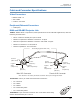
DMX and RS-485 Projector Link
Cables: Belden 9841 or equivalent (meets specifications for EIA RS-485 applications) with the
following characteristics:
• Two 4-conductor twisted pairs plus a shield
• Maximum capacitance between conductors: 30 pF/ft
• Maximum capacitance between conductor and shield: 55 pF/ft
• Maximum resistance: 20 Ohm/100 ft
• Nominal impedance: 100–140 Ohm
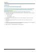
positive
(data true)*
negative
(data
complement)*
Common
(cable shield)
Male XLR Connector
Female XLR Connector
positive
(data true)
negative
(data
complement)
XLR shell
Common
(cable shield)
positive
(data true)*
negative
(data complement)*
negative
(data
complement)
positive
(data true)
*This data line is not used by the fixture, but allows data to pass through the fixture.
Grounding lug (inside XLR shell)
2
1
3
1
2
3
4
5
5
4
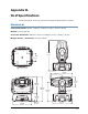
Connectors: Two 5-pin male and female XLR connectors:
•Pin 1 Ground
•Pin 2 Data–
•Pin 3 Data+
1
2
0
Ω
1
2
3
4
5
•Pin 4 Secondary data–
•Pin 5 Secondary data+
Terminator: 5-pin male XLR connector with a 120 Ohm terminating
resistor fitted between pins 2 and 3.