
DL.2 Digital Light User Manual


CHAPTER 2
Setup and Configuration
6 DL.2 Digital Light User Manual
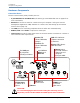
Hardware Components
Connection Ports
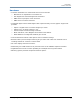
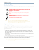
The DL.2 fixture’s back panel provides ports for:
• 5-pin DMX Data In and Data Out (see Setting up a Standard DMX Link on page 10 for
more information)
• Ethernet to connect to other DL.2 fixtures and your computer running the Content
Management Application (CMA) software on a fixture link (see Setting up an Ethernet
Fixture Link on page 11).
•Two USB ports for connecting peripheral drives to assist with troubleshooting
• RGBHV, VGA and S-Video In options for video input.
• Camera Out provides S-Video output from the internal camera to another DL.2 fixture or
other external video output device.
CAUTION:
To avoid damaging the fixture and voiding the warranty, do not
physically connect to the RGBHV and VGA inputs at the same time.
USB 1
100-120 V;
50-60Hz; 7A
200-240 V;
50-60Hz; 3.5 A
USB 2
S-Video Output
S-Video In
VGA Input for
external source
RGBHV input
for external
video source.
5-pin DMX512
Data In and
to another DL.2
fixture
Two USB ports
for peripherals
including hard drives
Ethernet port to
connect DL.2 fixtures
to fixture link and
a computer
running the CMA
Receive LED
Link LED indicates
Data Out
Activity LED indicates
Transmit LED
indicates DMX data
coming in
indicates DMX data
going out
CMA connection
hardware connection
via Ethernet