MVP-SVR Power Saver Valve Controller MVP-SVR Open Loop Power Saver Valve Controller High Country Tek, Inc. reserves the right to improve this product at any time and without notice. This manual may contain mistakes and printing errors. The content is regularly checked and updated. Please check our website or contact our customer support for latest version. HCT accepts NO liability for technical mistakes or printing errors or their consequence.
MVP-SVR Power Saver Valve Controller Contents Welcome .................................................................................................................................................................... 3 Product Application Guidelines .................................................................................................................................. 4 MVP-SVR Controller ...........................................................................................................
MVP-SVR Power Saver Valve Controller Welcome Welcome to High Country Tek Inc. HCT is North America’s foremost independent designer and producer of modular, ruggedized digital and analog electronic controllers for the fluid power industry. From our factory in California, we manufacture ‘specialty’ controllers for specific functions and the user programmable ‘DVC family’ to enable large area networked system solutions. The modules are used in mobile, industrial and marine applications.
MVP-SVR Power Saver Valve Controller Product Application Guidelines ALWAYS do the following FULLY read this manual and accompanying data sheets BEFORE starting. Isolate this unit from all other equipment BEFORE any form of welding. Isolate the controller from ANY form of battery charging or battery boosting. Be aware of the electrical & mechanical connections, and the expected reactions of the equipment. Operate the units within the temperature range.
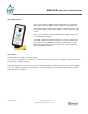
MVP-SVR Power Saver Valve Controller MVP-SVR Controller The MVP-SVR controller drives proportional solenoid valves with high starting current then reduces it to a lower operating level. Operating power is reduced thereby saving energy, reducing heat and extending coil life. Once configured, the settings are permanently stored in the controller memory.
MVP-SVR Power Saver Valve Controller Physical Description There are two indicator LEDs: STATUS and OUTPUT. The STATUS LED is green when the applied voltage is within the operating range. The OUTPUT LED is yellow and the brightness will vary with the output current. In the case of a fault the STATUS LED will flash red with a flash code. See Fault Status for details. The MVP communicates with the Graphical User Interface through an infrared interface port to RS232.
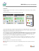
MVP-SVR Power Saver Valve Controller Configuration The GUI has 4 buttons (ran from a PC): Lock, Unlock, Up, and Down. There are short-cut keys: ‘/’(lock), ‘*’(unlock), ‘+’(up), and ‘-‘(down). The HCT Hand Held Interface has the same 4 buttons and 2-line LCD. Use the up and down arrows to navigate through the parameter list. The display will show the next parameter in the list when pressed. The parameter name is on the first line and the value is on the second line.
MVP-SVR Power Saver Valve Controller “Read settings from controller” displays a static table of values from non-volatile memory. The changes made to the settings by selecting “lock” are not updated in the table unless “read settings from controller” is selected again. To save the settings into a file for future use, click “read settings from controller” before clicking “save settings to file”. 021-MVP-SVR Rev A MVP-SVR User Manual Copyright © High Country Tek, Inc.
MVP-SVR Power Saver Valve Controller When uploading settings from a data file, the static table shows the settings from the data file, but they are not in the controller yet. Click “write settings to controller” before clicking “read settings from controller”. After this step, the static table displays the MVP-SVR settings from the data file. 021-MVP-SVR Rev A MVP-SVR User Manual Copyright © High Country Tek, Inc.
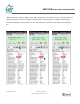
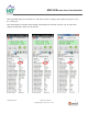
MVP-SVR Power Saver Valve Controller Parameter List The following table outlines the MVP-SVR parameters as well as the limits and units of measure for each parameter. Parameter Limits Units MVP-SVR-xxx Start time Start current Hold current Version # 0.0 to 6.0 Seconds 0 to 600 * mA 0 to 600 * mA Output current mA Supply voltage Volts Fault status Fault * 0 to 1.2A for –12A version, 0 to 2.5A for –25A version MVP-SVR-xxx - The title parameter is fixed.
MVP-SVR Power Saver Valve Controller Wiring Order Information The following is a break-down of the MVP part numbering system: MVP-SVR-06A-10F 10F = 10ft cable 20F & 30F standards 06A = 600mA output 25A = 2500mA output Required Communication Cables: For the Hand Held Interface Device: P/N: CBL-IRA For the PC software SAM: PN: CBL-IRMU P/N: CBL-IRA 021-MVP-SVR Rev A P/N: CBL-IRMU MVP-SVR User Manual Copyright © High Country Tek, Inc.
MVP-SVR Power Saver Valve Controller Application Examples Single Solenoid Control The MVP can drive a single solenoid. Set the dither and output settings according to the valve specifications. +V Power Input 9 - 28VDC FUSE Brown PWR + Blue GND Prop. PWM (Sourcing) MVP-SVR Electronic Valve Controller Connector GND GRN/YEL Screen Output Current Start current Hold current Seconds start time MVP-SVR 021-MVP-SVR Rev A MVP-SVR User Manual Copyright © High Country Tek, Inc.
MVP-SVR Power Saver Valve Controller - - or a full list of authori ed distributors worldwide, please visit or customer service, pricing, order placement and application support, contact us through E-mail at A N Hydraulics C ompany old lat Court Nevada City, CA, Tel ( ) a ( )